Juniper JN0-481 Data Center - Specialist (JNCIS-DC) Exam Practice Test
Data Center - Specialist (JNCIS-DC) Questions and Answers
You are allowed to assign tags for which three objects? (Choose three.)
Options:
Virtual networks
Interfaces
Generic systems
Property sets
Device profiles
Answer:
A, B, CExplanation:
In Apstra, tags are an intent-level metadata mechanism used to classify objects and drive automation and reuse. Within a data center blueprint, Apstra supports tagging multiple blueprint objects so operators can apply configuration or policy logic conditionally (for example, applying a connectivity template or a configlet based on a tag match). In this scenario, three valid taggable objects are virtual networks, interfaces, and generic systems.
Virtual network tagging is supported directly from the blueprint’s virtual network table, enabling you to label virtual networks (such as “finance,” “pci,” or “dev”) and then reference those tags elsewhere in blueprint operations and policy application. Interface tagging is also explicitly supported in the blueprint, allowing you to assign tags to switch interfaces and use those tags to control how templates, assignments, or other intent-driven operations apply to those ports. Finally, generic systems (which are modeled endpoint systems such as servers or external routers represented as “systems” in the blueprint) can be tagged so that downstream intent logic can distinguish system roles and apply the correct operations consistently across expansions and changes.
By contrast, property sets are structured data objects used for variable substitution and probe/configlet parameterization, not a primary target for operational tagging in the blueprint UI; and device profiles are catalog artifacts describing hardware/NOS compatibility rather than blueprint objects typically tagged for intent application.
Verified Juniper sources (URLs):
https://www.juniper.net/documentation/us/en/software/apstra5.1/apstra-user-guide/topics/topic-map/tag-interface-add-remove-datacenter.html
https://www.juniper.net/documentation/us/en/software/apstra5.0/apstra-user-guide/topics/task/tag-virtual-network-update.html
https://www.juniper.net/documentation/us/en/software/apstra5.0/apstra-user-guide/topics/topic-map/tag-system-add-remove-freeform.html
You want to make a widget appear on the main dashboard in Juniper Apstra. In this scenario, which statement is correct?
Options:
When creating the widget, select the Add to Blueprint Dashboard option.
On the blueprint dashboard, click on the Add Widget option.
Widgets automatically appear on the blueprint dashboard.
Set the Default toggle switch to On for the desired widget.
Answer:
DExplanation:
In Juniper Apstra, a widget is a graphical element that displays data from an intent-based analytics (IBA) probe. A widget can be used to monitor different aspects of the network and raise alerts to any anomalies. A widget can be viewed by itself or added to an analytics dashboard. A dashboard is a collection of widgets that can be customized and organized according to the user’s preference1.
The main dashboard in Juniper Apstra is the blueprint dashboard, which is the default view that shows the network information and configuration for the active blueprint. A blueprint is a logical representation of the network design and intent. The blueprint dashboard can display the system-generated dashboards, the user-generated dashboards, and the individual widgets that are relevant to the network2.
To make a widget appear on the main dashboard in Juniper Apstra, the user needs to set the Default toggle switch to On for the desired widget. This will add the widget to the blueprint dashboard, where it can be viewed along with other network information. The user can also remove the widget from the blueprint dashboard by setting the Default toggle switch to Off for the widget3. Therefore, the statement D is correct in this scenario.
The following three statements are incorrect in this scenario:
When creating the widget, select the Add to Blueprint Dashboard option. This is not true, because there is no such option when creating a widget in Juniper Apstra. The user can only select the widget type, the probe, and the display mode when creating a widget4. To add the widget to the blueprint dashboard, the user needs to set the Default toggle switch to On for the widget after creating it3.
On the blueprint dashboard, click on the Add Widget option. This is not true, because there is no such option on the blueprint dashboard in Juniper Apstra. The user can only view, edit, or delete the existing widgets and dashboards on the blueprint dashboard2. To add a widget to the blueprint dashboard, the user needs to set the Default toggle switch to On for the widget from the widgets table view3.
Widgets automatically appear on the blueprint dashboard. This is not true, because widgets do not automatically appear on the blueprint dashboard in Juniper Apstra. The user needs to manually add the widgets to the blueprint dashboard by setting the Default toggle switch to On for the widgets that they want to see on the blueprint dashboard3. The only exception is the widgets that are part of the system-generated dashboards, which are automatically created and added to the blueprint dashboard based on the state of the active blueprint2.
When creating a probe, an operator wants to make it easy to view that probe’s output. In this scenario, which element must be created to accomplish this task?
Options:
A dashboard widget
A predefined probe
A processor
A stage
Answer:
AExplanation:
In Apstra IBA, a probe is a directed graph made of stages (data you can inspect) and processors (operations that transform/aggregate data). While stages can be inspected during probe construction, the simplest operational way to make probe results readily consumable by day-2 operators is to publish them through widgets that can be placed on Analytics dashboards. A dashboard widget is the visualization and presentation object that renders either (1) counts of anomalies or (2) the outputs produced by stages and processors in a probe. Creating a widget tied to the probe output means the operator can open a dashboard and immediately see the metric trends, tables, or anomaly indicators without navigating into probe internals.
A predefined probe is optional content (a starting template) and is not required for visibility. Processors and stages are internal probe building blocks, but they do not, by themselves, create an operator-friendly view in the UI. In a Junos v24.4 EVPN-VXLAN fabric, this is especially useful for link utilization, drops, latency signals, or any custom telemetry pipeline: you build the probe logic once, then expose the key results in a widget that persists across operational workflows and can be shared on standardized dashboards for capacity planning and troubleshooting.
Verified Juniper sources (URLs):
https://www.juniper.net/documentation/us/en/software/apstra4.2/apstra-user-guide/topics/concept/widgets.html
https://www.juniper.net/documentation/us/en/software/apstra4.2/apstra-user-guide/topics/topic-map/widget-stage-create.html
https://www.juniper.net/documentation/us/en/software/apstra4.2/apstra-user-guide/topics/concept/probes.html
What is the primary reason for creating an Apstra worker node?
Options:
To support more than one blueprint
To create a space for storing event logs
To run Zero Touch Provisioning (ZTP)
To offload off-box agents and Intent-Based Analytics (IBA)
Answer:
DExplanation:
In Apstra 5.1, the worker node’s primary purpose is to add scalable runtime capacity to an Apstra cluster by hosting off-box services that would otherwise consume resources on the controller. Specifically, worker nodes run containerized services such as off-box device agents (used to communicate with and manage devices) and Intent-Based Analytics (IBA) components (such as probes and analytics-related services). This design keeps the controller node focused on cluster management and control-plane functions (API handling, cluster-wide state, blueprint control workflows), while shifting resource-intensive operational services to worker nodes.
As your fabric grows—more switches, more telemetry, more devices requiring agent connectivity—CPU and memory demand increases notably, especially when IBA is enabled. Adding worker nodes allows you to scale those container workloads horizontally without redesigning the fabric or reducing analytics coverage. In a Juniper data center built on EVPN-VXLAN with Junos v24.4 leaf-spine roles, this separation helps ensure that Apstra can continuously validate intent, process streaming telemetry, and maintain device communications reliably at scale. Worker nodes therefore exist primarily to offload and scale operational agents and IBA services, improving performance and resilience for larger deployments.
You have an EVPN-VXLAN data center IP fabric, with all single-homed hosts/servers. Which two EVPN route types are present in this scenario? (Choose two.)
Options:
Type 3
Type 7
Type 2
Type 4
Answer:
A, CExplanation:
In an EVPN-VXLAN fabric where all hosts are single-homed (each endpoint is attached to only one leaf/VTEP), the EVPN control plane still needs to advertise endpoint reachability and enable BUM handling across the overlay. Two EVPN route types are fundamental in this case: Type 2 and Type 3.
EVPN Route Type 2 (MAC/IP Advertisement) is used to advertise learned MAC addresses and, optionally, associated IP addresses for endpoints connected to the local leaf. This enables remote VTEPs to learn where a given host resides (which VTEP to send unicast traffic to) without relying on data-plane flooding for MAC learning. In Junos v24.4 EVPN-VXLAN deployments, Type 2 routes are the core mechanism for distributing endpoint reachability (MAC and MAC+IP bindings) within the EVPN domain.
EVPN Route Type 3 (Inclusive Multicast Ethernet Tag / IMET) is used to establish the flooding scope for BUM traffic in EVPN-VXLAN. In VXLAN fabrics that use ingress replication (common in data centers), Type 3 routes help build the list of remote VTEPs that should receive replicated BUM traffic for a given segment.
By contrast, Type 4 (Ethernet Segment) routes are associated with EVPN multihoming (ESI-based) and DF election; with only single-homed hosts, Type 4 is not required. Type 7 is not part of the baseline single-homed EVPN-VXLAN host advertisement set in this context.
Verified Juniper sources (URLs):
https://www.juniper.net/documentation/us/en/software/junos/evpn/topics/concept/evpn-bgp-multihoming-overview.html
https://www.juniper.net/documentation/us/en/software/junos/evpn/topics/topic-map/assisted-replication-evpn.html
You are performing an upgrade to your switches in your network. You want to ensure that the upgrade can be performed without interrupting traffic. In the Juniper Apstra UI, which deploy mode should be used to accomplish this task?
Options:
Deploy
Undeploy
Drain
Ready
Answer:
CExplanation:
In Apstra, Deploy Mode = Drain is the operational mechanism used to gracefully remove a switch from active forwarding before performing maintenance such as an OS upgrade. Drain mode is specifically intended to drain traffic while preserving fabric stability, so that maintenance can be executed with minimal to no application impact, provided the fabric design has sufficient redundancy (for example, ECMP in the underlay and dual-homing/ESI for server attachments). In an EVPN-VXLAN IP fabric, taking a leaf or spine abruptly out of service can cause transient loss of reachability as underlay adjacencies reconverge and the overlay recalculates paths. By placing the device into Drain, Apstra adjusts intent so that traffic is shifted away from the device as much as possible, reducing dependency on it before the upgrade begins.
This is different from Undeploy, which removes Apstra-rendered configuration and is generally used for decommissioning; if a device is carrying traffic, Apstra guidance is to drain first. Ready is a pre-deploy state used in lifecycle workflows, not a maintenance traffic-shifting mode. Deploy keeps the device fully participating. Therefore, for a maintenance window where the goal is “upgrade with minimal interruption,” the correct mode is Drain, then perform the Junos v24.4 upgrade, and finally return the device to Deploy.
Verified Juniper sources (URLs):
https://www.juniper.net/documentation/us/en/software/apstra4.2/apstra-drain-mode/apstra-drain-mode.pdf
https://www.juniper.net/documentation/us/en/software/apstra4.2/apstra-user-guide/topics/topic-map/deploy-mode-update-datacenter.html
https://www.juniper.net/documentation/us/en/software/apstra6.0/apstra-user-guide/topics/topic-map/device-config-lifecycle.html
What are two agent processes that operate within the Juniper Apstra device agent? (Choose two.)
Options:
Routing agent
Authentication agent
Telemetry agent
Deployment agent
Answer:
C, DExplanation:
In Apstra deployments that use on-box device agents, the agent package installs multiple processes inside the switch’s NOS namespace to provide an isolated runtime environment for Apstra control and telemetry collection. Two of those processes are the Telemetry Agent and the Deployment Agent. The Telemetry Agent is responsible for collecting operational information from the device—such as LLDP neighbor details, routing-related state, and interface information—and sending that telemetry upstream to Apstra. This telemetry is a key input for closed-loop assurance in EVPN-VXLAN fabrics, where Apstra correlates underlay health (interfaces, neighbors, sessions) with overlay services.
The Deployment Agent is responsible for receiving configuration content pushed from Apstra and applying it on the device. In a Junos v24.4 fabric, this is the component that enables Apstra to converge device configuration to the blueprint’s intent (for example, BGP underlay, EVPN signaling, and VXLAN constructs) without requiring manual CLI workflows. Both agents are typically idle most of the time, becoming active when Apstra needs to apply configuration changes or when significant state changes trigger telemetry updates.
Other listed options—“routing agent” and “authentication agent”—are not the named Apstra device-agent processes described for the on-box agent package in Juniper documentation.
Verified Juniper sources (URLs):
https://www.juniper.net/documentation/us/en/software/apstra4.2/apstra-server-and-security-guide/topics/concept/apstra-device-agents.html
What are two types of virtual networks defined inside Juniper Apstra software? (Choose two.)
Options:
VLAN
L3 VPN
VXLAN
L2 VPN
Answer:
A, CExplanation:
In Apstra 5.1, a Virtual Network (VN) is Apstra’s abstraction for a Layer 2 forwarding domain that groups endpoints into a logical segment across the fabric. Apstra defines virtual networks as being constructed using either VLANs or VXLANs. A VLAN-based VN represents a Layer 2 domain identified by a VLAN ID and is typically used where you want traditional VLAN semantics (often in smaller environments, migration scenarios, or designs where an overlay is not required). A VXLAN-based VN represents the same Layer 2 intent but uses a VXLAN VNI for scalable overlay segmentation, which is the common approach in EVPN-VXLAN data center fabrics.
In an IP fabric architecture, VXLAN provides encapsulation to carry tenant segments over the routed underlay, while EVPN provides the control-plane signaling for MAC/IP reachability. Junos v24.4 leaf devices act as VTEPs, mapping local VLANs/bridge-domains to VNIs and participating in EVPN for advertisement and convergence. Apstra’s VN construct allows you to create the segment once (as VLAN or VXLAN type), then consistently attach it to racks, ports, and endpoints through intent-driven workflows (such as connectivity templates and virtual network assignments).
“L2 VPN” and “L3 VPN” are service provider terms and are not the VN “types” in Apstra’s data center reference design. In Apstra, tenant L3 separation is modeled by routing zones (VRFs), while the VN itself is specifically either VLAN-based or VXLAN-based.
Verified Juniper sources (URLs):
https://www.juniper.net/documentation/us/en/software/apstra5.1/apstra-user-guide/topics/concept/virtual-networks.html
https://www.juniper.net/documentation/us/en/software/apstra5.1/apstra-user-guide/topics/topic-map/virtual-network-create.html
You are trying to deploy a five-stage template to a blueprint as shown in the exhibit. You cannot see your template name in the list of available templates.
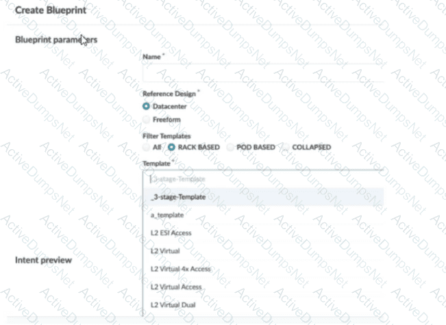
In this scenario, which statement is correct?
Options:
The Collapsed option should be selected.
You must include “five-stage” in the template name for it to appear in the list.
The Pod Based option should be selected.
Only Freeform-type blueprints support five-stage templates.
Answer:
CExplanation:
In Apstra 5.1, templates are organized by template type, and the Create Blueprint screen can filter the template list by those types. A five-stage Clos design in Apstra is represented as a pod-based template (multi-pod fabric with an additional tier such as super-spines to interconnect pods). Because of that, a five-stage template will only appear in the template selector when the Pod Based filter is chosen. If the filter is set to Rack Based or Collapsed, Apstra hides pod-based templates because those types correspond to different topology classes: rack-based aligns with a three-stage leaf–spine pod, while collapsed aligns with a spine-less topology pattern.
This behavior is by design to prevent selecting an incompatible template for the intended topology. The template name itself does not need to contain “five-stage”; Apstra determines its type from how the template was created and stored in the catalog. Also, five-stage templates are not limited to Freeform blueprints—five-stage is a data center fabric topology choice, and it is supported within the data center reference design workflows when the appropriate template type is selected.
So, to make the five-stage template visible and selectable, choose Pod Based in the template filter.
You are attempting to attach the server connected to the my_border_001_leaf1 node’s ge-0/0/5 interface to the finance-app virtual network.
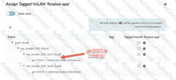
Referring to the exhibit, what would you do to solve the problem?
Options:
You can add a generic system to the physical topology.
You can set the generic system to the deploy mode.
You can allocate an IP pool resource to the virtual network.
You can assign the finance-app virtual network to the my_border_001_leaf1 node.
Answer:
AExplanation:
In Apstra 5.1, servers are modeled as Generic Systems and must be represented in the blueprint topology so that Apstra can bind an endpoint (the server) to a specific switch interface and then apply the intended connectivity template / virtual network attachment. In the exhibit, the interface ge-0/0/5 on my_border_001_leaf1 is shown as missing from the assignment workflow, which indicates that Apstra does not currently have an endpoint object connected to that port in the blueprint’s staged physical topology (or that the port is not presented as an eligible connectivity point for server attachment).
The correct remediation is to add a Generic System connected to my_border_001_leaf1 ge-0/0/5 in Staged > Physical > Topology, thereby creating a modeled server link on that interface. Once the Generic System exists and the interface is a recognized server-facing connectivity point, you can assign the Tagged VXLAN “finance-app” connectivity template (or the VN assignment action driven by that template) to the server-facing interface and then commit the staged changes.
Changing “deploy mode” may affect whether Apstra actively configures a generic system-facing link, but it does not solve a missing interface in the topology model. Likewise, allocating an IP pool is unrelated to making the port available for attachment, and assigning the VN to the switch node is not how server interfaces are attached in this workflow.
Verified Juniper sources (URLs):
https://www.juniper.net/documentation/us/en/software/apstra5.1/apstra-user-guide/topics/topic-map/internal-generic-system-create.html
https://www.juniper.net/documentation/us/en/software/apstra5.0/apstra-user-guide/topics/topic-map/virtual-network-assignment-update.html
https://cloudlabs.apstra.com/labguide/Cloudlabs/6.0.0/test-drive-guide/lab1-junos-11_adding-gs.html
What are two available Juniper Apstra template types? (Choose two.)
Options:
Collapsed
Rack-based
Compressed
Device-based
Answer:
A, BExplanation:
In Juniper Apstra 5.1, a template is a design abstraction used to create a blueprint. It captures the intended topology shape and design rules without tying the design to a specific vendor’s CLI. Apstra supports multiple template types to match common data center fabric architectures.
A rack-based template is used for the standard three-stage Clos (leaf–spine) approach. In this model, you define the spine logical devices and one or more rack types (containing leaf devices and optional endpoint constructs). This is the dominant pattern for EVPN-VXLAN IP fabrics: leaf switches provide server attachment, VXLAN encapsulation (VTEP function), and optional IRB gateways, while spines provide high-capacity L3 transit with ECMP.
A collapsed template is used for a spine-less (spineless) topology. Instead of a separate spine tier, a collapsed design models a fabric where leaf nodes interconnect in a mesh-like arrangement (as supported by the template type) to provide underlay reachability and redundancy. This can be useful for smaller environments or edge data centers where a full spine tier is unnecessary.
“Compressed” and “device-based” are not Apstra template types. Junos v24.4 is relevant when the blueprint is instantiated and deployed, but the template type selection is an Apstra design-time decision that determines the fabric topology class.
You are assigning managed devices to a blueprint, for a fully functioning IP fabric. In the Juniper Apstra UI, which mode should you choose for this task?
Options:
Deploy
Ready
Not Set
Drain
Answer:
AExplanation:
In Apstra, Deploy mode is the state in which a device is intended to fully participate in the fabric. For a three-stage eBGP IP Clos (typical EVPN-VXLAN underlay), “fully functioning” means the switch receives the complete, intent-derived configuration required for production operation—underlay interface addressing, BGP peering, routing policy constructs, and any overlay-related prerequisites appropriate for its role (leaf, spine, border leaf). In Apstra’s device configuration lifecycle, Deploy is the mode that causes Apstra to render and apply the full set of intended services for that node so it becomes an active member of the IP fabric and contributes to ECMP pathing and control-plane adjacency.
By contrast, Ready is commonly used when you want the device discovered and prepared (for example, basic identity and interface readiness), but not actively routing in the fabric. Drain is a maintenance state used to gracefully withdraw an already-deployed device from forwarding to minimize impact (for example, for upgrades or repairs). Not Set indicates the deploy mode has not been chosen and therefore does not represent an operationally complete participation state.
Therefore, when your objective is an operational IP fabric where the assigned devices are actively routing and forwarding according to blueprint intent on Junos v24.4, the correct choice is Deploy.
What does VXLAN use to uniquely label and identify broadcast domains?
Options:
VLAN ID
Agent Circuit Identifier (ACI)
Virtual Network Identifier (VNI)
End System Identifier (ESI)
Answer:
CExplanation:
In a VXLAN overlay, each Layer 2 broadcast domain (the logical equivalent of a VLAN/bridge domain) is identified by a 24-bit VXLAN Network Identifier (VNI) carried in the VXLAN header. This VNI is what allows the overlay to scale far beyond traditional VLAN space (12-bit VLAN IDs), enabling up to ~16 million distinct segments. In an EVPN-VXLAN data center fabric, Junos v24.4 leaf switches operate as VTEPs and map local bridge domains (often associated with VLANs on server-facing ports) to a VNI. When traffic is sent across the routed underlay, the leaf encapsulates Ethernet frames into VXLAN packets and inserts the VNI so the receiving VTEP can place the frame into the correct broadcast domain on decapsulation.
Apstra 5.1 abstracts this mapping through virtual networks and resource allocation: when you define a VXLAN-based virtual network, Apstra allocates a VNI from the appropriate pool and consistently programs the necessary constructs on all participating leaves. The key point is that VNI is the unique identifier in the VXLAN data plane used to label the broadcast domain across the IP fabric; VLAN IDs may exist locally at the edge for tagging, but the globally significant overlay identifier is the VNI.
Verified Juniper sources (URLs):
https://www.juniper.net/documentation/us/en/software/junos/evpn/topics/topic-map/sdn-vxlan.html
In Juniper Apstra, which statement about resources is correct?
Options:
User-defined resources are supported.
The scope of a pool is limited to a single blueprint.
The scope of a pool can be defined as global or blueprint specific.
Only the default resources are supported globally.
Answer:
CExplanation:
In Apstra 5.1, “resources” are the identifier values consumed by the fabric design and rendered into device configuration—examples include ASNs, IP addresses, VNIs, VLAN-related identifiers (where applicable), and similar allocation-driven values. These values are provided through resource pools, which are the authoritative containers Apstra draws from when assigning resources to blueprint roles (for example, leaf ASNs, spine ASNs, loopbacks, point-to-point subnets, and VNI ranges). A key architectural feature is that resource pools are not confined to one blueprint. Apstra supports pools with different scopes to match operational needs: some pools are managed centrally and reused across multiple blueprints, while other pools are created and used within the context of a specific blueprint when you want strict separation and lifecycle alignment with that blueprint.
This is why the correct statement is that a pool’s scope can be global or blueprint-specific. Global pools are appropriate when you want consistent allocation policy across fabrics (for example, enterprise-wide ASN ranges). Blueprint-specific pools are appropriate when you want per-fabric independence or when allocations are generated dynamically within the blueprint. This scope behavior is independent of Junos v24.4; Junos receives the final rendered values, but the pool scoping and allocation control are Apstra design-time constructs that ensure deterministic, conflict-free assignments at scale.
Verified Juniper sources (URLs):
https://www.juniper.net/documentation/us/en/software/apstra5.1/apstra-user-guide/topics/concept/resources.html
https://www.juniper.net/documentation/us/en/software/apstra5.1/apstra-user-guide/topics/concept/freeform-resource-management.html
https://www.juniper.net/documentation/us/en/software/apstra5.1/apstra-user-guide/topics/ref/resource-pools-api.html
An operator is working on a capacity-planning exercise. The operator needs to examine the pre-built time-series information regarding link utilization. In the Juniper Apstra UI, which top-level tab would the operator have to access to find this information?
Options:
Active
Staged
Analytics
Dashboard
Answer:
CExplanation:
In Apstra 5.1, capacity planning based on pre-built time-series telemetry (such as link utilization trends) is part of Intent-Based Analytics (IBA). IBA is where Apstra ingests streaming telemetry from fabric devices, stores it as time-series data, and presents it through built-in analytics views (dashboards/widgets) and probes. Because the question specifically calls out “pre-built time series information regarding link utilization,” the correct UI location is the Analytics top-level tab within the blueprint.
The Active tab is primarily oriented to operational state and day-2 workflows (for example, viewing live state, queries, and device-level operational views). The Staged tab is where you modify intent (physical/virtual design, policies, catalog items) prior to committing and deploying. The Dashboard provides a high-level blueprint overview and navigation, but the drill-down and time-series analytics views that support trending and capacity analysis are accessed via Analytics.
In an EVPN-VXLAN fabric using Junos v24.4, link utilization time-series is particularly valuable because underlay congestion can degrade overlay performance (BGP convergence behavior, ECMP distribution effectiveness, and endpoint experience). Apstra’s Analytics tab centralizes these metrics so operators can evaluate utilization baselines, identify sustained hot links, and support proactive actions (rebalancing, adding capacity, or adjusting design intent) without relying on ad-hoc per-device CLI polling.
Verified Juniper sources (URLs):
https://www.juniper.net/documentation/us/en/software/apstra5.1/apstra-custom-telemetry-collection-guide/topics/concept/apstra-telemetry-and-intent-based-analytics.html
You are building a blueprint using Juniper Apstra and must change the cable map to match the physical environment. Where in the blueprint UI is this task accomplished?
Options:
Active → Physical → Links
Staged → Physical → Links
Active → Connectivity Templates
Staged → Connectivity Templates
Answer:
BExplanation:
In Apstra 5.1, the cabling map is part of the blueprint’s intended physical topology. Cable-map edits are performed in the Staged workspace because Staged is where you modify intent (what the fabric should look like) before committing those changes and deploying them. The Staged → Physical → Links view provides both a tabular and topology-oriented representation of spine-to-leaf and other physical connections. When Apstra auto-assigns interfaces during initial build, the logical mapping may not match the real patching in the data center. The cabling map editor allows you to override interface names (and where applicable, link addressing metadata) so the blueprint accurately reflects the actual patch panel and switchport usage.
This accuracy is critical in a Junos v24.4 leaf-spine fabric because underlay correctness depends on the real physical adjacencies: link membership, LAG expectations (where used), and the resulting BGP neighbor relationships that carry EVPN signaling for VXLAN overlays. By updating the cabling map in Staged, you ensure Apstra can correctly validate neighbor discovery, verify intent, and produce consistent device configuration aligned to the real-world wiring. After making the cabling corrections, you commit the staged changes and then deploy/apply so that Apstra’s intent and the running network converge. This work is not performed under Active (which reflects deployed state) and is not a function of Connectivity Templates (which are for endpoint/service attachment rather than fabric cabling).
Verified Juniper sources (URLs):
https://www.juniper.net/documentation/us/en/software/apstra5.0/apstra-user-guide/topics/topic-map/cabling-map-edit-datacenter.html
https://www.juniper.net/documentation/us/en/software/apstra6.0/apstra-user-guide/topics/topic-map/cabling-map-edit-datacenter.html
https://www.juniper.net/documentation/us/en/software/jvd/jvd-dcfabric-5-stage/configuration_walkthrough.html
What is the purpose of an EVPN Ethernet segment identifier (ESI)?
Options:
To provide a hop count between devices
To identify Layer 2 frame types for filtering purposes
To specify a BGP community
To prevent loops within a LAG connection
Answer:
DExplanation:
In EVPN multihoming, the Ethernet Segment Identifier (ESI) is the mandatory identifier used to represent a multihomed Ethernet segment—for example, a server or downstream switch that is dual-homed to two leaf devices using a single logical LAG/port-channel. By assigning the same ESI to the participating leaf-facing interfaces, the fabric recognizes those links as belonging to one Ethernet segment and can apply EVPN multihoming procedures consistently across the pair.
A key outcome of EVPN multihoming is loop prevention for multi-attached Layer 2 domains. EVPN uses the Ethernet segment concept (identified by the ESI) along with Designated Forwarder (DF) election to ensure that only the appropriate device forwards BUM (broadcast, unknown unicast, multicast) traffic toward the multihomed segment, avoiding duplicate forwarding and L2 loops. In addition, ESI-based multihoming supports resilient forwarding behavior during failures (for example, link or node loss) while maintaining correct advertisement and convergence in the EVPN control plane.
Therefore, among the provided options, the purpose that best matches how ESI is used operationally is to prevent loops within a LAG/multihomed connection, which is fundamental to EVPN-VXLAN data center designs on Junos v24.4 leaf devices and is also explicitly supported by Apstra when modeling ESI-based dual-homing.
Verified Juniper sources (URLs):
https://www.juniper.net/documentation/us/en/software/nce/evpn-lag-multihoming-guide/topics/concept/evpn-lag-guide-introduction.html
https://www.juniper.net/documentation/us/en/software/nce/evpn-lag-multihoming-guide/topics/task/evpn-lag-guide-esi-types-lacp.html
https://www.juniper.net/documentation/us/en/software/junos/evpn/topics/topic-map/evpn-mh-df-election.html
Which attribute enables Juniper Apstra to scale and manage thousands of devices with a single server instance?
Options:
Apstra is installed as a cloud resource.
Apstra is based on NGINX.
Apstra is available as an OVA.
Apstra is a distributed state system.
Answer:
DExplanation:
The attribute that enables Juniper Apstra to scale and manage thousands of devices with a single server instance is that Apstra is a distributed state system. This means that Apstra uses a graph database to store the network topology and configuration data in a distributed and replicated manner across multiple server nodes. This allows Apstra to handle large-scale networks with high performance, reliability, and availability. Apstra also uses a stateful orchestration engine that ensures the network state is always consistent with the intent of the blueprint, which is the logical representation of the network design and behavior. Apstra can automatically detect and resolve any discrepancies between the desired and actual network state, as well as handle any changes or failures in the network. The other options are incorrect because:
A. Apstra is installed as a cloud resource is wrong because Apstra can be installed either as a cloud resource or as an on-premises resource. Apstra is available as a virtual machine image that can be deployed on various hypervisors, such as VMware ESXi, QEMU/KVM, Microsoft Hyper-V, or Oracle VirtualBox. Apstra can also be deployed on public cloud platforms, such as Amazon Web Services (AWS) or Microsoft Azure. However, the installation method does not affect the scalability of Apstra, which is determined by the distributed state system architecture.
B. Apstra is based on NGINX is wrong because Apstra is not based on NGINX, but on Python and Django. NGINX is a web server and reverse proxy that Apstra uses to serve the web user interface and the REST API. However, NGINX is not the core component of Apstra, and it does not affect the scalability of Apstra, which is determined by the distributed state system architecture.
C. Apstra is available as an OVA is wrong because Apstra is available as an OVF, not an OVA. An OVF (Open Virtualization Format) is a standard format for packaging and distributing virtual machine images. An OVA (Open Virtual Appliance) is a single file that contains the OVF and the virtual disk images. Apstra provides an OVF file that can be imported into various hypervisors, such as VMware ESXi, QEMU/KVM, Microsoft Hyper-V, or Oracle VirtualBox. However, the availability of Apstra as an OVF does not affect the scalability of Apstra, which is determined by the distributed state system architecture. References:
JUNIPER APSTRA ARCHITECTURE
Apstra Server Requirements/References
Juniper Networks Apstra 4.0 enhances the experience of users and operators
Juniper Apstra provides five different predefined user roles. Given this information, what is the main difference between the administrator and the user role?
Options:
The user role can only be assigned to specific blueprints.
The user role can make changes to any other role.
The user role cannot make any changes to other user types.
The user role can only make changes to the view role.
Answer:
CExplanation:
Apstra role-based access control separates fabric operations from identity and authorization administration. The administrator role includes full permissions, including the ability to manage users and roles (for example, creating users, assigning permissions, and creating/cloning/editing custom roles where allowed). This enables administrators to govern who can access the system and what they are permitted to change across all blueprints and system settings.
The user role, in contrast, is designed for day-to-day fabric work: viewing and editing supported blueprint elements and operational objects within the scope permitted by the role, but not administering other users’ access or modifying the role structure itself. In other words, a user can work on the network intent and operations, but cannot elevate privileges, change other users’ roles, or otherwise manage user/role administration unless explicitly granted additional permissions through custom roles.
That makes option C the correct statement: the user role cannot make changes to other user types (that is, it lacks the permissions needed to administer identities/roles). Options A, B, and D do not reflect Apstra’s RBAC model: roles are not primarily constrained “per blueprint” in that way, and users are not intended to modify other roles—those are administrator-level capabilities.
Verified Juniper sources (URLs):
https://www.juniper.net/documentation/us/en/software/apstra6.0/apstra-user-guide/topics/concept/user-role-management.html
https://www.juniper.net/documentation/us/en/software/apstra4.2/apstra-user-guide/topics/concept/user-role-management.html
https://www.juniper.net/documentation/us/en/software/apstra5.0/apstra-user-guide/topics/concept/user-role-management.html
Unlock JN0-481 Features
- JN0-481 All Real Exam Questions
- JN0-481 Exam easy to use and print PDF format
- Download Free JN0-481 Demo (Try before Buy)
- Free Frequent Updates
- 100% Passing Guarantee by Activedumpsnet
Questions & Answers PDF Demo
- JN0-481 All Real Exam Questions
- JN0-481 Exam easy to use and print PDF format
- Download Free JN0-481 Demo (Try before Buy)
- Free Frequent Updates
- 100% Passing Guarantee by Activedumpsnet