Juniper JN0-480 Data Center Specialist (JNCIS-DC) Exam Practice Test
Data Center Specialist (JNCIS-DC) Questions and Answers
You want to add a configuration that is not supported by Juniper Apstra reference architecture using a configlet.
Which two configurations would be applicable in this scenario? (Choose two.)
Options:
static route configuration
policy configuration
syslog configuration
NTP configuration
Answer:
C, DExplanation:
According to the Juniper documentation1, a configlet is a configuration template that augments Apstra’s reference design with non-native device configuration. They consist of one or more generators. Each generator specifies a NOS type (config style), when to render the configuration, and CLI commands (and file name as applicable). Some applications for configlets include the following:
- Syslog
- SNMP access policy
- TACACS / RADIUS
- Management ACLs
- Control plane policing
- NTP
- Username / password
Therefore, the correct answer is C and D. syslog configuration and NTP configuration. These are examples of non-native device configuration that can be added using a configlet. Static route configuration and policy configuration are not applicable in this scenario, because they are part of the reference design configuration that should not be replaced or modified by a configlet. References: Configlets (Datacenter Design), Configlet Examples (Design)
When an agent installation is successful, devices are placed into which state using the Juniper Apstra Ul?
Options:
IS-MAINT
OOS-READY
OOS-QUARANTINED
IS-ACTIVE
Answer:
CExplanation:
When an agent installation is successful, devices are placed into the Out of Service Quarantined (OOS-QUARANTINED) state using the Juniper Apstra UI. This state means that the device is not yet managed by Apstra and has not been assigned to any blueprint. The device configuration at this point is called Pristine Config. To make the device ready for use in a blueprint, you need toacknowledge the device, which changes its state to Out of Service Ready (OOS-READY)12. References:
- Managing Devices
- AOS Device Configuration Lifecycle
Using Juniper Apstra. which component is defined in a template?
Options:
the leaf-to-spine interconnection
the speed of the links between the spine devices and the leaf devices
the number of spine devices in a topology
the definition of IP pools
Answer:
AExplanation:
According to the Juniper documentation1, a template is a configuration template that defines a network’s policy intent and structure. A template can be either rack-based or pod-based, depending on the type and number of racks and pods in the network design. A template includes the following details:
- Policies: These are the parameters that apply to the entire network, such as the overlay control protocol, the ASN allocation scheme, and the underlay type.
- Structure: This is the physical layout of the network, such as the type and number of racks, pods, spines, and leaves. The structure also defines the leaf-to-spine interconnection, which is the number and type of links between the leaf and spine devices. The leaf-to-spine interconnection can be either single or dual, depending on the redundancy and bandwidth requirements.
Therefore, the correct answer is A. the leaf-to-spine interconnection. This is a component that is defined in a template, as it determines the physical connectivity of the network. The speed of the links, the number of spine devices, and the definition of IP pools are not components that are defined in a template, as they are either derived from the device profiles, the resource pools, or the blueprint settings. References: Templates Introduction | Apstra 4.2 | Juniper Networks
You use Juniper Apstra to enable a new VXLAN virtual network.
Which two components would be automatically derived in this situation? (Choose two.)
Options:
IP subnet
VLAN-ID
VXLAN VNI
Route Zone
Answer:
A, CExplanation:
According to the Juniper documentation1, a VXLAN virtual network is a collection of Layer 2 forwarding domains that span multiple racks in a fabric. A VXLAN virtual network requires a name and a VXLAN network identifier (VNI), which is a 24-bit number that identifies the virtual network. The VNI can be either explicitly assigned or auto-assigned from a resource pool. A VXLAN virtual network can also have Layer 3 connectivity, which enables routing between different VNIs within a routing zone. A routing zone is an L3 domain that isolates the IP traffic of different tenants. A routing zone can have one or more VNIs associated with it. To enable Layer 3 connectivity, a VXLAN virtual network needs an IP subnet, which is a range of IP addresses that can be assigned to the hosts in the virtual network. The IP subnet can be either explicitly assigned or auto-assigned from a resource pool. Therefore, the correct answer is A and C. IP subnet and VXLAN VNI are two components that would be automatically derived when enabling a new VXLAN virtual network using Juniper Apstra. References: Virtual Networks | Apstra 4.1 | Juniper Networks
You are installing a Juniper Apstra server in your data center. You have multiple users that will be expected to configure, manage, and carry out operational tasks in your data center. You have decided to implement remote user authentication for the role-based access control of your Apstra server.
In this scenario, which three methods are supported? (Choose three.)
Options:
TACACS+
LDAP
RADIUS
SAML
Auth0
Answer:
A, B, CExplanation:
To implement remote user authentication for the role-based access control of your Apstra server, you can use one of the following methods: TACACS+, LDAP, or RADIUS. These are the protocols that Juniper Apstra supports to authenticate and authorize users based on roles assigned to individual users within an enterprise. You can configure the Apstra server to use one or more of these protocols as the authentication sources and specify the order of preference. You can also configure the Apstra server to use local user accounts as a fallback option if the remote authentication fails. The other options are incorrect because:
- D. SAML is wrong because SAML (Security Assertion Markup Language) is not a supported protocol for remote user authentication for the role-based access control of your Apstra server. SAML is an XML-based standard for exchanging authentication and authorization data between different parties, such as identity providers and service providers. SAML is commonly used for web-based single sign-on (SSO) scenarios, but it is not compatible with the Apstra server.
- E. Auth0 is wrong because Auth0 is not a protocol, but a service that provides authentication and authorization solutions for web and mobile applications. Auth0 is a platform that supports various protocols and standards, such as OAuth, OpenID Connect, SAML, and JWT. Auth0 is not a supported service for remote user authentication for the role-based access control of your Apstra server. References:
- User Authentication Overview
- [Juniper Apstra] Authentication and Authorization Debugging1
- Authenticate User (API)
- Configure Apstra Server
Exhibit.
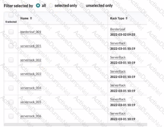
Referring to the exhibit, how many tack types ate used in the staged blueprint?
Options:
six
three
seven
two
Answer:
DExplanation:
Referring to the exhibit, the image shows the Racks table under the Staged menu in the Juniper Apstra UI. The Racks table displays the details of the racks that are used in the blueprint, such as the name, rack type, and date. The rack type is a resource that defines the type and number of leaf devices, access switches, and/or generic systems that are used in rack builds1. The image shows seven racks in the table, but only two rack types: BorderLeaf and ServerRack. Therefore, the statement D is correct in this scenario.
The following three statements are incorrect in this scenario:
- A. six. This is not true, because there are not six rack types in the table, but only two. The number six corresponds to the number of racks that have the same rack type: ServerRack.
- B. three. This is not true, because there are not three rack types in the table, but only two. The number three does not correspond to any relevant information in the table or the image.
- C. seven. This is not true, because there are not seven rack types in the table, but only two. The number seven corresponds to the total number of racks in the table, not the rack types.
References:
- Rack Types (Datacenter Design)
- Racks (Staged)
Which two actions are required during Juniper Apstra's deploy phase? (Choose two.)
Options:
Assign device profiles to the blueprint.
Assign user roles to the blueprint.
Assign interlace maps to the blueprint.
Assign resources to the blueprint.
Answer:
A, DExplanation:
The deploy phase is the final step in the Juniper Apstra data center fabric design and deployment process. In this phase, you apply the Apstra-rendered configuration to the devices and verify the intent of the blueprint. Based on the web search results, we can infer the following actions are required during the deploy phase12:
- Assign device profiles to the blueprint. This action associates a specific vendor model to each logical device in the blueprint. Device profiles contain extensive hardware model details, such as form factor, ASIC, CPU, RAM, ECMP limit, and supported features. Device profiles also define how configuration is generated, how telemetry commands are rendered, and how configuration is deployed on a device. Device profiles enable the Apstra system to render and deploy the configuration according to the Apstra Reference Design34.
- Assign resources to the blueprint. This action allocates the physical devices, IP addresses, VLANs, and ASNs to the logical devices, networks, and routing zones in the blueprint. Resources can be assigned manually or automatically by the Apstra system. Assigning resources ensures that the blueprint has all the necessary elements to generate the configuration and deploy the fabric5 .
- Assign user roles to the blueprint. This action is not required during the deploy phase. User roles are defined at the system level, not at the blueprint level. User roles determine the permissions and access levels of different users in the Apstra system. User roles can be system-defined or custom-defined .
- Assign interface maps to the blueprint. This action is not required during the deploy phase. Interface maps are defined at the design phase, not at the deploy phase. Interface maps are objects that map the logical interfaces of a logical device to the physical interfaces of a device profile. Interface maps enable the Apstra system to generate the correct interface configuration for each device in the fabric . References:
- Deploy
- Deploy Device
- Device Profiles
- Juniper Device Profiles
- Resources
Exhibit.
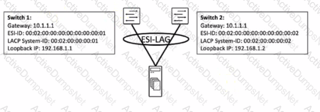
You are working to build an ESI-LAG for a multihomed server. The ESI-LAG is not coming up as multihomed.
Referring to the exhibit, what are two solutions to this problem? (Choose two.)
Options:
The gateway IP addresses on both devices must be different.
The LACP system ID on both devices must be the same.
The loopback IP addresses on both devices must be the same.
The ESI ID on both devices must be the same.
Answer:
B, DExplanation:
According to the Juniper documentation1, an ESI-LAG is a link aggregation group (LAG) that spans two or more devices and is identified by an Ethernet segment identifier (ESI). An ESI-LAG provides redundancy and load balancing for a multihomed server in an EVPN-VXLAN network. To configure an ESI-LAG, you need to ensure that the following requirements are met:
- The LACP system ID on both devices must be the same. This ensures that the LACP protocol can negotiate the LAG parameters and form a single logical interface for the server.
- The ESI ID on both devices must be the same. This ensures that the EVPN control plane can advertise the ESI-LAG as a single Ethernet segment and synchronize the MAC and IP addresses of the server across the devices.
- The VLAN ID and VNI on both devices must be the same. This ensures that the server can communicate with other hosts in the same virtual network and that the VXLAN encapsulation and decapsulation can work properly.
In the exhibit, the LACP system ID and the ESI ID on both devices are different, which prevents the ESI-LAG from coming up as multihomed. Therefore, the correct answer is B and D. The LACP system ID on both devices must be the same and the ESI ID on both devices must be the same. References: ESI-LAG Made Easier with EZ-LAG, Example: Configuring an ESI on a Logical Interface With EVPN-MPLS Multihoming, Introduction to EVPN LAG Multihoming
You are receiving cable, interface, and BGP anomalies from several devices within the data center fabric. In Juniper Apstra. how would you troubleshoot these types of errors?
Options:
In the Ul, go to Time Voyager and revert to the last working version.
In the Ul, access the console to the devices and review the interface states.
In the Ul, go to Devices and confirm that agent connectivity is fine.
In the Ul, verify device connectivity by consulting the cable map.
Answer:
DExplanation:
The cable map is a graphical representation of the physical connections between the devices in the data center fabric. It shows the status of the cables, interfaces, and BGP sessions for each device. You can use the cable map to identify and troubleshoot any cable, interface, or BGP anomalies that may occur in the fabric. You can also filter the cable map by device name, device type, device role, device state, cable state, interface state, or BGP state12. References:
- Cable Map Overview
- Cable Map User Guide
When working with logical devices, you specify where each port group is connected.
In thisscenario, which two Juniper Apstra Ul options are available to the operator? {Choose two.)
Options:
router
unused
generic
firewall
Answer:
B, CExplanation:
When working with logical devices, you specify where each port group is connected by selecting the port group layout and the port speed and role (s) for each port group. The Juniper Apstra UI offers two options to the operator for the port group role: unused and generic1.
- Unused: This option means that the port group is not configured or used by Apstra. This can be useful for ports that are faulty, reserved, or not part of the data center fabric1.
- Generic: This option means that the port group is configured with a generic role that is not specific to any device type or function. This can be useful for ports that are used for testing, troubleshooting, or custom purposes1. References:
- Logical Devices
Exhibit.
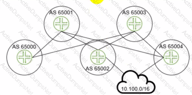
The 10.100.0.0/16 route is being advertised into your BGP IP fabric. ECMP load balancing has been properly enabled on all devices
In this scenario, how many routes will the leaf device in AS 65000 receive for the 10.100.0.0/16 prefix?
Options:
3
1
2
4
Answer:
AExplanation:
The leaf device in AS 65000 will receive three routes for the 10.100.0.0/16 prefix, one from each spine device in AS 65001, AS 65002, and AS 65003. Since ECMP load balancing is enabled, the leaf device will install all three routes in its routing table and distribute the traffic among them. The other options are incorrect because:
- B. 1 is wrong because the leaf device will not receive only one route for the prefix. It will receive multiple routes from different spine devices and use ECMP to load balance among them.
- C. 2 is wrong because the leaf device will not receive only two routes for the prefix. It will receive three routes from three spine devices, as explained above.
- D. 4 is wrong because the leaf device will not receive four routes for the prefix. It will receive three routes from three spine devices, as explained above. The fourth spine device in AS 65004 is not directly connected to the leaf device and will not advertise the prefix to it. References:
- IP Fabric Underlay Network Design and Implementation
- BGP Multipath load sharing iBGP and eBGP
- ECMP Load Balancing
What is the purpose of a Juniper Apstra rack?
Options:
It stores information on how pods connect to super spines.
It stores information on how leaf nodes connect to generic devices
It stores IP address and ASN pool information.
It stores device port data rates and vendor information.
Answer:
BExplanation:
A Juniper Apstra rack is a physical entity that contains one or more network devices, such as leaf nodes, access switches, or generic systems. A rack is used to organize and manage the network devices in the Apstra software application. A rack has the following characteristics:
- It stores information on how leaf nodes connect to generic devices. This is because a rack can include generic systems, which are devices that are not managed by Juniper Apstra, but are connected to the network. A generic system can be a server, a firewall, a load balancer, or any other device that has a networkinterface. A rack stores the information on how the leaf nodes, which are the devices that provide access to the end hosts, connect to the generic devices, such as the port number, the link speed, the LAG mode, and the roles1.
- It has a rack type, which defines the type and number of leaf devices, access switches, and/or generic systems that are used in the rack. A rack type is a resource that is created in the data center design phase, and it does not specify the vendor or the model of the devices. A rack type can be predefined or custom-made, and it can be used to create multiple racks with the same structure and configuration2.
- It has a rack build, which assigns the specific vendor and model of the devices to the rack. A rack build is created in the staged phase, and it uses the rack type as a template. A rack build can also assign the resources, such as the IP addresses, the ASNs, and the VNIs, to the devices in the rack3.
- It has a rack deployment, which applies the network configuration and services to the devices in the rack. A rack deployment is performed in the active phase, and it uses the rack build as a reference. A rack deployment can also monitor the network performance and compliance of the devices in the rack4.
The following three statements are incorrect in this scenario:
- It stores information on how pods connect to super spines. This is not true, because a rack does not store any information on the pod or the super spine level of the network. A pod is a cluster of leaf and spine devices that form a 3-stage Clos topology, and a super spine is a device that connects multiple pods in a 5-stage Clos topology. A rack only stores information on the leaf and the access level of the network1.
- It stores IP address and ASN pool information. This is not true, because a rack does not store any information on the IP address and ASN pools. IP address and ASN pools are resources that are created in the data center design phase, and they contain a range of IP addresses and ASNs that can be assigned to the devices and the virtual networks. A rack only uses the IP address and ASN pools to assign the resources to the devices in the rack build2.
- It stores device port data rates and vendor information. This is not true, because a rack does not store any information on the device port data rates and vendor information. The device port data rates and vendor information are specified in the rack build, which assigns the specific vendor and model of the devices to the rack. A rack only uses the rack build to apply the network configuration and services to the devices in the rack deployment3.
References:
- Racks (Staged)
- Rack Types (Datacenter Design)
- Rack Builds (Staged)
- Racks (Active)
In the Juniper Apstra Ul. which two resource types would be created in the Resources menu? (Choose two.)
Options:
bridge domain identifier (BDI)
DHCP pools
ASN pools
IP pools
Answer:
C, DExplanation:
According to the Juniper documentation1, the Resources menu in the Juniper Apstra UI allows you to create and manage various types of resources that are assigned to different elements of the network. Resources include the following types:
- IPv4 (including Host IPv4)
- IPv6 (including Host IPv6)
- ASN (autonomous system number)
- VNI (virtual network identifier)
- VLAN (virtual local area network)
- Integer (used for pool type VLAN in local pools in Freeform blueprints)
Therefore, the correct answer is C and D. ASN pools and IP pools are two types of resources that can be created in the Resources menu. Bridge domain identifier (BDI) and DHCP pools are not applicable in this scenario, because they are not part of the resources types supported by Juniper Apstra. References: Resources Introduction | Apstra 4.1 | Juniper Networks
In the Juniper Apstra design phase, which object dictates port count, port speed, and how the ports would be used?
Options:
logical devices
rack type
network devices
interface map
Answer:
DExplanation:
Interface maps are objects that map interfaces between logical devices and physical hardware devices in the Juniper Apstra design phase. They dictate port count, port speed, and how the ports would be used for achieving the intended network configuration rendering. Interface maps also allow you to select device ports, transformations, and interfaces, provision breakout ports, and disable unused ports. For more information, see Interface Maps (Datacenter Design). References:
- Interface Maps (Datacenter Design)
- Design
- Interface Maps Introduction
Exhibit.
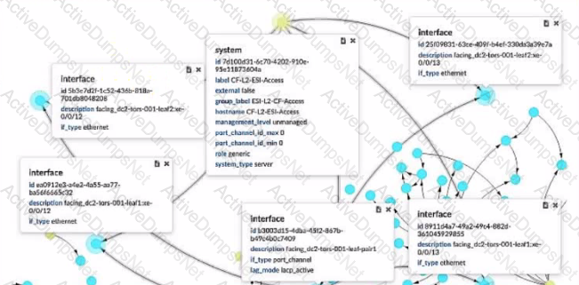
Which two statements ate correct about the information shown in the exhibit? (Choose two.)
Options:
The system is fully managed by Juniper Apstra.
The device shown is a generic system.
Four physical interfaces exist in a LAG facing the leaf pair.
The physical ports are not part of the LAG.
Answer:
B, CExplanation:
According to the Juniper documentation1, a generic system is a device that is not managed by Juniper Apstra and does not have a specific role or type assigned to it. A generic system can be used to represent a server, a firewall, a load balancer, or any other device that is not part of the fabric. In the exhibit, the device shown is a generic system, as indicated by its role, system type, and management level. Therefore, the correct answer is B. The device shown is a generic system.
According to the Juniper documentation2, a LAG is a link aggregation group that bundles multiple physical interfaces into a single logical interface. A LAG can provide increased bandwidth, redundancy, and load balancing for the network traffic. In the exhibit, the device shown has four physical interfaces that are part of a LAG, as indicated by their description and li_type. The LAG is facing the leaf pair, which are the two switches that connect to the device. Therefore, the correct answer is C. Four physical interfaces exist in a LAG facing the leaf pair. References: Generic Systems (Datacenter Design), Form LAG | Apstra 4.1 | Juniper Networks
Using the Juniper Apstra multitenancy capabilities, which approach will allow a tenant to interconnect two different routing zones?
Options:
Interconnection is the default behavior.
Use interconnection through the fabric spine nodes.
Interconnection cannot be enabled.
Use interconnection through an external gateway.
Answer:
DExplanation:
According to the Juniper documentation1, a routing zone is an L3 domain, the unit of tenancy in multi-tenant networks. You create routing zones for tenants to isolate their IP traffic from one another, thus enabling tenants to re-use IP subnets. In addition to being in its own VRF, each routing zone can be assigned its own DHCP relay server and external system connections. You can create one or more virtual networks within a routing zone, which means a tenant can stretch its L2 applications across multiple racks within its routing zone. For virtual networks with Layer 3 SVI, the SVI is associated with a Virtual Routing and Forwarding (VRF) instance for each routing zone isolating the virtual network SVI from other virtual network SVIs in other routing zones. If you’re using multiple routing zones, external system connections must be from leaf switches in the fabric. Routing between routing zones must be accomplished with external systems. Therefore, the correct answer is D. Use interconnection through an external gateway. References: Routing Zones
Exhibit.
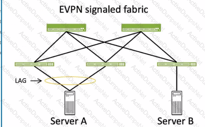
Which two statements about ESI values are correct for the server connections to the fabric shown in the exhibit? (Choose two.)
Options:
A valid ESI value for Server A is 0x00.00.00.00.00.00.00.00.00.00.
A valid ESI value for Server B is 0x00.20.20.20.20.20.20.20.20.20.
A valid ESI value for Server A is 0x00.10.10.10.10.10.10.10.10.10.
A valid ESI value for Server B is 0x00.00.00.00.00.00.00.00.00.00.
Answer:
C, DExplanation:
To answer this question, we need to understand the concept of ESI values in EVPN LAGs. An ESI is a 10-byte value that identifies an Ethernet segment, which is a set of links that connect a multihomed device (such as a server) to one or more PE devices (such as leaf switches) in an EVPN network. The same ESI value must be configured on all the PE devices that connect to the same Ethernet segment. This allows the PE devices to form an EVPN LAG, which supports active-active or active-standby multihoming for the device. The ESI value can be manually configured (type 0) or automatically derived from LACP (type 1) or other methods. In the exhibit, Server A is connected to two leaf switches (QFX 5210) using a LAG with LACP enabled. Server B is connected to three leaf switches (QFX 5120) using a LAG with LACP enabled. Based on this information, the following statements are correct about ESI values for the server connections to the fabric:
- C. A valid ESI value for Server A is 0x00.10.10.10.10.10.10.10.10.10. This is true because this ESI value can be automatically derived from the LACP configuration on the QFX 5210 devices. The LACP system ID is usually based on the MAC address of the device, and the LACP administrative key is a 2-byte value that identifies the LAG. For example, if the MAC address of the QFX 5210 device is 00:10:10:10:10:10 and the LAG ID is 10, then the LACP system ID is 00:10:10:10:10:10 and the LACP administrative key is 00:0A. The ESI value is then derived by concatenating the LACP system ID and the LACP administrative key, resulting in 00:10:10:10:10:10:00:0A. This ESI value can be represented in hexadecimal notation as 0x00.10.10.10.10.10.00.0A, or padded with zeros as 0x00.10.10.10.10.10.00.0A.00.00. This ESI value must be configured on both QFX 5210 devices that connect to Server A.
- D. A valid ESI value for Server B is 0x00.00.00.00.00.00.00.00.00.00. This is true because this ESI value is a reserved value that indicates a single-homed device. Server B is connected to three leaf switches (QFX 5120) using a LAG, but it is not multihomed to any of them. This means that Server B does not need an ESI value to form an EVPN LAG with any of the leaf switches. Instead, Server B can use the reserved ESI value of 0x00.00.00.00.00.00.00.00.00.00, which indicates that it is a single-homed device and does not participate in any EVPN LAG. This ESI value must be configured on all three QFX 5120 devices that connect to Server B. Thefollowing statements are incorrect about ESI values for the server connections to the fabric:
- A. A valid ESI value for Server A is 0x00.00.00.00.00.00.00.00.00.00. This is false because this ESI value is a reserved value that indicates a single-homed device. Server A is connected to two leaf switches (QFX 5210) using a LAG with LACP enabled, which means that it is multihomed to both of them. This means that Server A needs an ESI value to form an EVPN LAG with the leaf switches. The ESI value must be unique and non-zero for each Ethernet segment, so the reserved ESI value of 0x00.00.00.00.00.00.00.00.00.00 is not valid for Server A.
- B. A valid ESI value for Server B is 0x00.20.20.20.20.20.20.20.20.20. This is false because this ESI value is not derived from the LACP configuration on the QFX 5120 devices. Server B is connected to three leaf switches (QFX 5120) using a LAG with LACP enabled, but it is not multihomed to any of them. This means that Server B does not need an ESI value to form an EVPN LAG with any of the leaf switches. Instead, Server B can use the reserved ESI value of 0x00.00.00.00.00.00.00.00.00.00, which indicates that it is a single-homed device and does not participate in any EVPN LAG. The ESI value of 0x00.20.20.20.20.20.20.20.20.20 is not valid for Server B, and it may cause conflicts with other Ethernet segments that use the same ESI value. References:
- Ethernet Segment Identifiers, ESI Types, and LACP in EVPN LAGs
- Understanding Automatically Generated ESIs in EVPN Networks
- Ethernet Segment in EVPN: All You Need to Know
Which statement is correct about the Juniper Apstra Rendered configuration?
Options:
It is built at commit time and stored in a MySQL database.
It is stored in a NoSQL database and incrementally updated.
It is dynamically tendered at commit time.
It is rendered from the graph database and stored locally.
Answer:
CExplanation:
The Juniper Apstra Rendered configuration is the configuration that is generated from the staged blueprint and applied to the devices in the network. The Rendered configuration is dynamically rendered at commit time, which means that it is created on the fly based on the latest changes and validations in the blueprint. The Rendered configuration is not stored in any database, but it can be viewed in the Apstra UI or downloaded as a file. The Rendered configuration reflects the desired state of the network as defined by the intent of the blueprint. The other options are incorrect because:
- A. It is built at commit time and stored in a MySQL database is wrong because the Rendered configuration is not stored in any database, let alone a MySQLdatabase. Apstra uses a graph database to store the network topology and configuration data, not a relational database like MySQL.
- B. It is stored in a NoSQL database and incrementally updated is wrong because the Rendered configuration is not stored in any database, let alone a NoSQL database. Apstra uses a graph database to store the network topology and configuration data, not a non-relational database like NoSQL. The Rendered configuration is not incrementally updated, but dynamically rendered at commit time.
- D. It is rendered from the graph database and stored locally is wrong because the Rendered configuration is not rendered from the graph database, but from the staged blueprint. The graph database stores the network topology and configuration data, but the Rendered configuration is generated from the blueprint, which is a logical representation of the network design and intent. The Rendered configuration is not stored locally, but it can be downloaded as a file if needed. References:
- Config Rendering in Juniper Apstra
- AOS Device Configuration Lifecycle
- Configlets (Datacenter Design)
InJuniper Apstra. which three modes are available fordevices? (Choose three.)
Options:
Deploy
Active
Stopped
Drain
Ready
Answer:
A, D, EExplanation:
Juniper Apstra supports three deploy modes for devices: Deploy, Drain, and Ready. These modes determine the configuration and state of the devices in the data center fabric12.
- Deploy: This mode applies the full Apstra-rendered configuration to the device, according to the Apstra Reference Design. The device state becomes IS-ACTIVE and the device is ready to carry traffic in the fabric12.
- Drain: This mode adds a “drain” configuration to the device, which prevents any new traffic from entering the device. The device state becomes IS-READY and the device is prepared for maintenance or decommissioning12.
- Ready: This mode removes the Apstra-rendered configuration from the device, leaving only the basic configuration such as device hostname, interface descriptions, and port speed/breakout. The device state becomes IS-READY and the device is not part of the fabric12. References:
- Device Configuration Lifecycle
- Set Deploy Mode (Datacenter)
Unlock JN0-480 Features
- JN0-480 All Real Exam Questions
- JN0-480 Exam easy to use and print PDF format
- Download Free JN0-480 Demo (Try before Buy)
- Free Frequent Updates
- 100% Passing Guarantee by Activedumpsnet
Questions & Answers PDF Demo
- JN0-480 All Real Exam Questions
- JN0-480 Exam easy to use and print PDF format
- Download Free JN0-480 Demo (Try before Buy)
- Free Frequent Updates
- 100% Passing Guarantee by Activedumpsnet