Juniper JN0-364 Service Provider Routing and Switching - Specialist (JNCIS-SP) Exam Practice Test
Service Provider Routing and Switching - Specialist (JNCIS-SP) Questions and Answers
You must ensure that your routing platform with redundant REs continues to forward packets, even if one RE fails. Which technology would you use to accomplish this task?
Options:
NSB
LAG
BFD
GRES
Answer:
DExplanation:
For Juniper platforms equipped with dualRouting Engines (REs), the fundamental technology required to provide high availability during a hardware or software failure of the primary RE isGraceful Routing Engine Switchover (GRES).
According to Juniper Networks technical documentation, GRES allows the backup RE to stay in a "hot" standby state. When GRES is enabled, the primary RE synchronizes critical state information with the backup RE, specifically thechassis stateand theinterface state. This synchronization includes the Packet Forwarding Engine (PFE) configuration.
When the primary RE fails, the backup RE takes over immediately. Because the PFE (which resides on the line cards) was already synchronized and is not restarted during the switchover, the routercontinues to forward packetsthat are already in flight or part of established flows. This prevents a complete network outage during an RE failover.
Comparison with other options:
NSB (Non-Stop Bridging - Option A):Focuses specifically on maintaining Layer 2 protocol states (like STP) during a switchover.
LAG (Link Aggregation - Option B):Provides redundancy for physical links, not the control plane or the RE.
BFD (Bidirectional Forwarding Detection - Option C):Is a protocol used for rapid detection of link or neighbor failures; it does not protect the RE or maintain forwarding during an internal switchover.
It is important to note that while GRES maintains theforwardingstate, it does not by itself maintain therouting protocolstate (adjacencies). To keep OSPF or BGP sessions from dropping during the switchover, GRES must be paired withNon-Stop Active Routing (NSR). However, as the question focuses on the core requirement of continuing to forward packets,GRESis the foundational technology.
Which IS-IS adjacency state indicates that hello packets have been exchanged but the adjacency is not yet fully established?
Options:
loading
initializing
up
two-way
Answer:
BExplanation:
In theIS-IS (Intermediate System to Intermediate System)protocol, the process of forming an adjacency between two neighbors follows a specific sequence of states. While OSPF uses states like "Init," "Two-Way," and "Full," IS-IS uses a slightly different nomenclature within its state machine.
According to Juniper Networks technical documentation, when a router first sends anIS-IS Hello (IIH) PDUand receives one back from a neighbor, but has not yet confirmed that the neighbor "sees" it back, the adjacency enters theInitializingstate. Specifically, on a point-to-point link, the state transitions fromDowntoInitializingas soon as the first PDU is received. On a broadcast network (like Ethernet), the Initializing state indicates that the local router has received a Hello PDU from the neighbor, but the local router's own System ID is not yet listed in the neighbor's list of "seen" neighbors (the neighbor's Hello PDU does not yet contain the local router's MAC address).
The adjacency only moves to theUpstate (Option C) once bi-directional communication is confirmed—meaning both routers have seen each other's System IDs in the incoming Hello PDUs.
Why other options are incorrect:
Loading (Option A):This is an OSPF state, not an IS-IS state. In IS-IS, database synchronization happens after the adjacency is Up.
Two-Way (Option D):While functionally similar to the state IS-IS is achieving, "Two-Way" is the specific terminology for OSPF. In IS-IS, the intermediate step between knowing a neighbor exists and having a fully functional adjacency is strictly calledInitializing.
Which IPv6 extension header is used to specify intermediate nodes for a packet's path?
Options:
hop-by-hop options
routing
fragment
destination options
Answer:
BExplanation:
In the IPv6 architecture, the base header is kept at a fixed size of 40 bytes to streamline processing. Any additional features or options are handled byExtension Headers, which are inserted between the IPv6 header and the upper-layer protocol. According to Juniper Networks technical documentation and RFC 8200, when a source node needs to list one or more intermediate nodes to be "visited" on the way to the final destination, it utilizes theRouting extension header (Option B).
The Routing header is functionally similar to the "Source Route" option in IPv4. When a packet contains a Routing header, it is addressed to the first intermediate node listed in the header. That node examines the header, swaps its own address with the next address in the list, and forwards the packet. This process continues until the packet reaches the final destination. This is a foundational component for technologies likeSegment Routing over IPv6 (SRv6), where the Routing header (specifically the Segment Routing Header or SRH) is used to steer traffic through a specific set of service instructions or nodes.
To distinguish this from the other options:
Hop-by-hop options (Option A):These carry information that must be examined byeverynode along the path (such as Router Alert), not just specific intermediate nodes.
Fragment (Option C):This is used only when the source node needs to fragment a packet that exceeds the path MTU.
Destination options (Option D):These carry optional information intended specifically for the destination node (or nodes listed in a Routing header), but they do not dictate the path themselves.
By default, which MPLS operation is performed by the penultimate router in an LSP on the transport label?
Options:
swap
push
rewrite
pop
Answer:
DExplanation:
In a Multiprotocol Label Switching (MPLS) environment, label operations are categorized into three primary actions:Push(adding a label),Swap(replacing a label), andPop(removing a label). The specific behavior described in the question refers to a mechanism calledPenultimate Hop Popping (PHP).
According to Juniper Networks technical documentation, the goal of PHP is to improve forwarding efficiency at the egress point of a Label-Switched Path (LSP). TheEgress Label Edge Router (LER), which is the final destination for the LSP, would normally have to perform two lookups if it received a labeled packet: first, it would look up the label in its MPLS table to see it is the destination, and second, it would look up the underlying IP payload in its IP routing table (inet.0) to forward the packet.
To alleviate this burden, the Egress LER signals a special label value calledImplicit Null (Label 3)to its upstream neighbor (the penultimate router) during the signaling process (RSVP or LDP). When thepenultimate routerreceives a packet destined for that egress LER, it sees the instruction to pop the transport label. Consequently, the penultimate router performs aPopoperation, stripping away the outer MPLS label and sending the raw IP packet (or the remaining inner service label) to the Egress LER.
This allows the Egress LER to perform only a single lookup. If the transport label was the only label, the Egress LER simply performs a standard IP lookup. If there is a VPN label remaining, it performs a single MPLS lookup for the VRF. This "default" behavior in Junos OS optimizes the performance of the egress router by offloading the final label removal to the penultimate hop. Note that ifUltimate Hop Popping (UHP)were configured (via the explicit-null command), the penultimate router would perform aSwapto Label 0 instead of a Pop.
Exhibit:
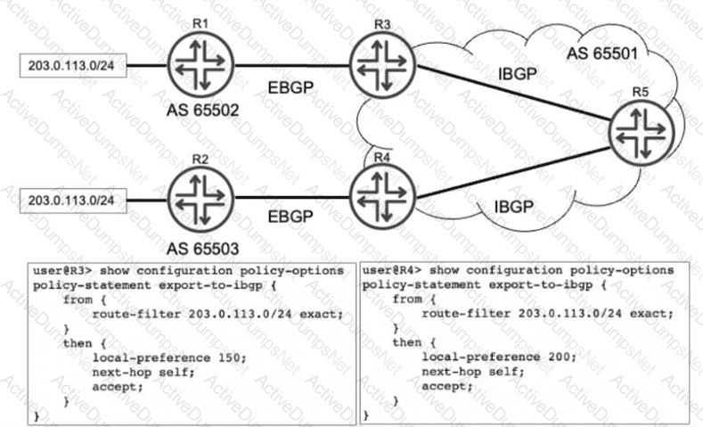
Referring to the exhibit, R1 and R2 are advertising the same prefix 203.0.113.0/24 to R3 and R4 over EBGP. R3 and R4 both advertise this prefix to R5. Which advertisement does R5 choose to install in its routing table?
Options:
The advertisement from R4 is chosen.
The advertisements from both R3 and R4, but R3 is chosen for forwarding.
The advertisement from R3 is chosen.
The advertisements from both R3 and R4, but R4 is chosen for forwarding.
Answer:
AExplanation:
In a Juniper Networks environment, when a router receives multiple BGP paths for the same destination prefix, it utilizes theBGP Path Selection Algorithmto determine the single "best" path to install in the routing table and advertise to other peers. This selection process follows a strict hierarchy of attributes.
According to Juniper Networks technical documentation, the very first attribute evaluated by the BGP process (after ensuring the next hop is reachable) is theLocal Preference. Local preference is a well-known discretionary attribute used to communicate a preference for a specific exit point from the local Autonomous System (AS). A higher local preference value is always preferred over a lower one.
Analyzing the exhibit:
R3receives the prefix from R1 and applies an export policy to its IBGP session that sets thelocal preference to 150.
R4receives the same prefix from R2 and applies an export policy to its IBGP session that sets thelocal preference to 200.
R5receives both of these IBGP updates from R3 and R4.
When R5 runs the best-path algorithm for the 203.0.113.0/24 prefix, it compares the local preference values. Since the path from R4 has a local preference of 200 and the path from R3 has a local preference of 150, R5 immediately selects the path fromR4as the best route. Because BGP is designed to prevent loops and maintain a consistent view, only this single best path is installed as the active route in R5's routing table (inet.0). Options B and D are incorrect because they imply multiple paths are installed for forwarding, which only occurs if specific multipath load-balancing is configured, which is not indicated here.
You are designing a high availability solution for a Juniper router with dual Routing Engines (RE). You want to ensure that the routing protocol state is preserved during an RE switchover. You have already enabled graceful Routing Engine switchover (GRES) and you want to avoid relying on helper routers to maintain the routing protocol state. In this scenario, which feature would accomplish this behavior?
Options:
non-stop active bridging
bidirectional forwarding detection
graceful restart
non-stop active routing
Answer:
DExplanation:
When designing High Availability (HA) for Juniper Service Provider routers, understanding the interaction between the control plane and data plane is vital. The user has already enabledGraceful Routing Engine Switchover (GRES), which synchronizes the interface and kernel state between the primary and backup Routing Engines (REs). However, GRES by itself does not preserve the routing protocol state (like OSPF adjacencies or BGP sessions).
To achieve the preservation of the routing protocol state without relying on external "helper" routers, you must implementNon-Stop Active Routing (NSR). According to Juniper Networks documentation, NSR uses the infrastructure provided by GRES to also synchronize the routing protocol process (rpd) information. Under NSR, the backup RE maintains a "hot" standby state of all routing protocols. If the primary RE fails, the backup RE takes over immediately. Because it already possesses the full routing table and peer session states, the peering neighbors are unaware that a switchover occurred. No protocol adjacency resets occur, and traffic continues to flow uninterrupted.
It is crucial to differentiate NSR fromGraceful Restart (Option C). While Graceful Restart also aims to maintain traffic flow during a switchover, itdoesrequire help from neighboring routers (known as "helper mode"). If the neighbors do not support or are not configured for Graceful Restart, the sessions will drop. Since the user explicitly stated they want to "avoid relying on helper routers," Graceful Restart is not the correct solution.
Non-stop Active Bridging (Option A)provides a similar "hitless" failover but specifically for Layer 2 environments (STP/VLANs) rather than Layer 3 routing protocols.BFD (Option B)is a failure detection protocol used to speed up convergence but does not preserve state during an RE failover; in fact, without NSR, BFD would likely trigger a faster teardown of the session during a switchover. Therefore,NSRis the only feature that meets the requirement for independent control-plane preservation.
Which two statements regarding GRE and IP-IP tunnels are correct? (Choose two.)
Options:
These tunnels add additional overhead to the packets that traverse them.
These tunnels do not add any overhead to the packets that traverse them.
These tunnels offer secure encryption mechanisms.
These tunnels do not offer encryption mechanisms.
Answer:
A, DExplanation:
In Juniper Networks Junos OS,Generic Routing Encapsulation (GRE)andIP-in-IP (IP-IP)are common tunneling mechanisms used to transport packets across a network by encapsulating them within another protocol. Understanding the header structure and the limitations of these protocols is essential for proper MTU (Maximum Transmission Unit) management and security design.
Overhead (Option A):
Both GRE and IP-IP tunnels operate by adding an additional IP header to the original packet. An IP-IP tunnel (Protocol 4) adds a20-byteIPv4 header. A GRE tunnel (Protocol 47) adds the same20-bytedelivery IP header plus a minimum4-byteGRE header (totaling 24 bytes, which can increase if keys or sequencing are used). Because these headers are added to the payload, the total size of the packet increases. This "overhead" means that if the original packet was already at the MTU limit (e.g., 1500 bytes), the encapsulated packet will exceed it, potentially leading to fragmentation or the need to adjust theTCP MSS (Maximum Segment Size).
Encryption (Option D):
Crucially, according to Juniper Service Provider documentation, neither GRE nor IP-IP provides nativeencryptionor data confidentiality. They are encapsulation protocols, not security protocols. The payload remains in cleartext and is visible to any device along the path. If security and encryption are required for data traversing these tunnels, they must be combined withIPsec (IP Security). While GRE is often used as the "carrier" for IPsec (to allow multicast or dynamic routing protocols which IPsec alone does not support), the GRE protocol itself remains an unencrypted delivery mechanism. Therefore, statements A and D accurately describe the architectural behavior of these tunnel types.
You are designing an MPLS network and want to ensure that traffic traverses an LSP between PE routers that follow an explicit path through the core. Which protocol would accomplish this task?
Options:
BGP
RSVP
IS-IS
LDP
Answer:
BExplanation:
In a Juniper Networks MPLS environment, the selection of a signaling protocol depends heavily on the requirement for traffic engineering and path control. To satisfy the requirement for anexplicit path—where the network architect defines specific hop-by-hop routers that the traffic must traverse—theResource Reservation Protocol (RSVP)is the necessary choice.
According to Juniper documentation, RSVP (specifically RSVP-TE) supports the use ofExplicit Route Objects (EROs). When you configure an LSP in Junos OS, you can define a path consisting of a series of IP addresses (strict or loose hops). RSVP then signals the LSP along that exact sequence of routers, reserving resources and establishing labels as it goes. This allows for precise control over the network's traffic patterns, enabling administrators to steer traffic away from congested links or toward specific high-bandwidth paths.
In contrast,LDP (Label Distribution Protocol)(Option D) is a "best-effort" signaling protocol. LDP strictly follows the Interior Gateway Protocol (IGP) shortest path. It does not support explicit paths or traffic engineering constraints; it simply builds a "mesh" of labels based on the existing routing table.IS-IS(Option C) is an IGP used to populate the routing table and TED but does not signal labels.BGP(Option A) is used for service delivery (like L3VPNs) but relies on an underlying transport LSP (built by RSVP or LDP) to reach its next hop. Therefore, only RSVP provides the mechanism for explicit path manipulation.
You are the administrator for two Junos routers called R1 and R2. These two routers are directly connected to each other. These two routers run IS-IS and BFD. R1 is configured to send BFD packets every 300 milliseconds. R2 is configured to send BFD packets every 400 milliseconds. In this situation, what is the expected outcome?
Options:
Each router will send BFD packets at the rate that has been locally configured.
BFD will fail due to the mismatched timers.
Each router will negotiate to send BFD packets at the slowest of the two rates.
Each router will negotiate to send BFD packets at the fastest of the two rates.
Answer:
CExplanation:
In the context of Juniper Networks High Availability,Bidirectional Forwarding Detection (BFD)is a lightweight protocol designed to provide fast failure detection for the forwarding path. Unlike the slow "hello" mechanisms found in IGPs like OSPF or IS-IS, BFD can detect link or neighbor failures in sub-second intervals.
According to Juniper Networks technical documentation, BFD operates through a negotiation process. When two routers establish a BFD session, they exchange their locally configuredMinimum Transmit IntervalandMinimum Receive Intervalwithin the BFD control packets. The fundamental rule of BFD negotiation is that the routers must agree on a common timing value that accommodates the slower of the two devices to ensure stability and prevent "false positives" (detecting a failure when none exists simply because one router cannot keep up with the processing speed).
In this scenario, R1 expects to send at 300ms, while R2 is configured for 400ms. During the handshake, R1 informs R2 it is capable of 300ms, but R2 informs R1 it can only support a minimum of 400ms. Consequently, the routers will negotiate to use theslowest of the two rates (400ms). Specifically, the transmission interval of one router is matched to the receive interval of the other. By choosing the highest common denominator (the slowest rate), the BFD session ensures that both routers have sufficient time to process incoming control packets. This negotiation allows BFD to be highly flexible in heterogeneous environments where different hardware platforms may have varying CPU capabilities for handling rapid heartbeat packets.
For two or more switches to participate in the same MSTP region, which parameter must match?
Options:
Region name
Extended system ID
Root bridge priority
Root bridge ID
Answer:
AExplanation:
Multiple Spanning Tree Protocol (MSTP), as defined in IEEE 802.1s and implemented in Juniper Networks Junos OS, allows for the grouping of VLANs into specific spanning tree instances. This provides significant scalability and load-balancing advantages over traditional STP or RSTP. To achieve this, switches must be grouped into logical "Regions."
According to Juniper documentation, for two or more switches to be considered part of the sameMSTP Region, they must possess an identicalMSTP Configuration Identifier. This identifier consists of three specific attributes that must match exactly across all participating switches:
MSTI Name (Region Name):A descriptive string (up to 32 characters) that identifies the region.
MSTI Revision Level:A numerical value (0–65535) used to track configuration changes.
VLAN-to-Instance Mapping:The specific table that defines which VLAN IDs are associated with which Multiple Spanning Tree Instances (MSTIs).
If even one of these parameters—such as theRegion name(Option A)—differs, the switches will treat each other as being in separate regions. When switches are in different regions, they interact using theCommon Spanning Tree (CST), effectively seeing the other region as a single "virtual bridge," which limits the granularity of traffic engineering.
TheExtended system ID(Option B) is a component of the Bridge ID used to carry VLAN information in PVST+ but is not a region-matching requirement.Root bridge priority(Option C) andRoot bridge ID(Option D) are variables used during the STP election process to determine the topology's root, but they do not define the boundaries of an MSTP region itself.
What are two types of BGP messages exchanged while in the Established state? (Choose two.)
Options:
open
request
update
notification
Answer:
C, DExplanation:
In theBorder Gateway Protocol (BGP)finite state machine (FSM), theEstablishedstate is the final and functional stage of a BGP peering session. According to Juniper Networks technical documentation, once a session reaches this state, the two peers have successfully exchanged Open messages and agreed upon session parameters (such as AS numbers, hold timers, and BGP identifiers). Only after the session is "Established" can the routers begin the actual exchange of network layer reachability information (NLRI).
The most frequent message type exchanged in the Established state is theUPDATEmessage. These messages are the heart of BGP operations; they are used to advertise new feasible routes to a peer or to withdraw routes that are no longer reachable. An UPDATE message contains path attributes (like AS-Path, Next-Hop, and Local Preference) and the associated prefixes. In a stable network, UPDATE messages are only sent when there is a change in the topology, adhering to BGP’s incremental update philosophy.
The second message type that can be exchanged in this state is theNOTIFICATIONmessage. While ideally, a session stays established, any detected error—such as a hold timer expiration, a malformed update, or a manual "clear" command—will trigger the transmission of a NOTIFICATION message. This message informs the peer of the specific error code and immediately causes the BGP session to transition back to the Idle state, tearing down the TCP connection.
It is important to note thatOPENmessages (Option A) are only used during the session initialization phase to transition from the OpenConfirm state to Established.REQUEST(Option B) is not a valid BGP message type defined in the standard (RFC 4271); the closest equivalent in functionality would be a Route-Refresh message, which is a separate extension. Therefore, in the context of standard BGP operations within the Established state, Updates and Notifications are the correct answers.
A BGP router receives two routes to the same prefix. One route has a higher local preference, while the other has a shorter AS path. In this scenario, which route would be selected?
Options:
The route with the shorter AS path.
The route with the higher local preference.
The route with the lower origin code.
The route with the lowest MED value.
Answer:
BExplanation:
TheBGP path selection algorithmis a deterministic process used by Juniper routers to select the single "best" path from the BGP table to be placed into the routing table (inet.0). This algorithm follows a specific, hierarchical set of rules. According to Juniper Networks technical documentation, the router evaluates attributes in a fixed order, and once a tie is broken at a specific step, the remaining steps are ignored.
The order of the primary BGP attributes in Junos OS is as follows:
Highest Local Preference:This is the first attribute evaluated after the basic check for a reachable next hop. Local preference is used within an Autonomous System (AS) to prioritize one exit point over another.
Shortest AS_PATH:If the local preference is equal, the router then evaluates the length of the AS_PATH attribute.
Lowest Origin Code:(IGP < EGP < Incomplete).
Lowest Multi-Exit Discriminator (MED).
In this specific scenario, the router compares a path with ahigher local preferenceagainst a path with ashorter AS path. Because theLocal Preferencecheck occurs at Step 1 and theAS_PATHcheck occurs later at Step 2, the router will select the path with the higher local preference immediately. The length of the AS path becomes irrelevant in this comparison because the tie was already broken by the local preference value. This allows network administrators to override the default "shortest path" logic of BGP to prefer specific providers or links based on business requirements.
Which two protocols would be used for dynamic routing in IPv6 environments? (Choose two.)
Options:
IGMP
IS-IS
OSPFv2
BGP
Answer:
B, DExplanation:
The transition to IPv6 requires routing protocols that are capable of carrying 128-bit address information. Juniper Networks Junos OS supports several "IPv6-ready" protocols for dynamic routing.
1. IS-IS (Option B):
As discussed in previous questions,IS-ISis inherently extensible due to its use ofTLVs (Type, Length, Value). To support IPv6, the protocol did not need a major rewrite; instead, new TLVs (such as TLV 236 for IPv6 reachability and TLV 232 for IPv6 interface addresses) were added. A single IS-IS process in Junos can simultaneously carry both IPv4 and IPv6 routing information, making it a highly efficient choice for "dual-stack" service provider backbones.
2. BGP (Option D):
BGP was updated to support multiple protocols throughMultiprotocol Extensions (MP-BGP), defined in RFC 4760. By usingAddress Family Identifiers (AFI)andSubsequent Address Family Identifiers (SAFI), a single BGP session can exchange NLRI (Network Layer Reachability Information) for IPv4 unicast, IPv6 unicast, and even VPNv4/VPNv6 routes. In Junos, this is configured under the family inet6 unicast hierarchy within the BGP protocols configuration.
Why other options are incorrect:
IGMP (Option A):This is a management protocol for IPv4 multicast (Internet Group Management Protocol). Its IPv6 equivalent isMLD (Multicast Listener Discovery).
OSPFv2 (Option C):OSPF version 2 is strictly for IPv4. To run OSPF in an IPv6 environment,OSPFv3must be used, as it was specifically redesigned to handle the IPv6 address space and link-local communication.
In OSPF, which three fields must match between neighbors before forming an adjacency? (Choose three.)
Options:
router priority
hello interval
network mask
dead interval
designated router
Answer:
B, C, DExplanation:
For OSPF routers to transition from the "Init" state to a full adjacency, they must agree on several parameters exchanged within theirHello packets. If these parameters do not match, the routers will refuse to form a neighbor relationship, a common point of failure in service provider networks.
According to Juniper Networks documentation, the following fields are mandatory matches:
Hello Interval (Option B):The frequency at which Hello packets are sent. Default is 10 seconds on broadcast networks.
Dead Interval (Option D):The time a router waits without receiving a Hello before declaring a neighbor down. Default is 4 times the Hello interval.
Network Mask (Option C):On broadcast and NBMA (Non-Broadcast Multi-Access) segments, the subnet masks must match because OSPF uses the mask to determine the network boundaries for the link-state advertisements.
Area ID:Routers must belong to the same logical OSPF area.
Authentication:If configured, the type and password/key must be identical.
Why other options are incorrect:
Router Priority (Option A):This is used to influence the election of the Designated Router (DR). It doesnotneed to match; in fact, different priorities are often used to ensure a specific router becomes the DR.
Designated Router (Option E):The DR is theresultof an election that happens after the initial Hello exchange. It is not a field that must match beforehand to start the process.
By ensuring the Hello/Dead timers and the Subnet Mask are synchronized, OSPF guarantees a stable and predictable environment for the subsequent exchange of Link-State Advertisements (LSAs).
Exhibit:
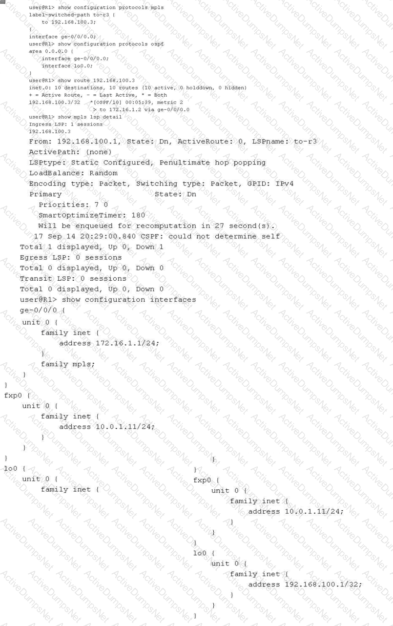
You have configured an MPLS LSP to 192.168.100.3. However, the LSP is in the down state. Referring to the exhibit, which two actions would solve this problem? (Choose two.)
Options:
Issue the set routing-options rib inet.3 static route 192.168.100.1 command and commit.
Issue the set protocols mpls label-switched-path to-r3 no-cspf command and commit.
Issue the set interfaces lo0 family mpls command on router R1 and commit.
Issue the set protocols ospf traffic-engineering command and commit.
Answer:
B, DExplanation:
In a Juniper Networks environment, establishing a functionalMultiprotocol Label Switching (MPLS)Label-Switched Path (LSP) requires synchronized control plane operations. According to Juniper technical documentation, the most common reason for an LSP to remain in the "Down" state at the ingress router is a failure of theConstrained Shortest Path First (CSPF)algorithm during the path computation phase.
The provided exhibit for routerR1reveals a critical error in the show mpls lsp detail output: "CSPF: could not determine self". This specific error indicates that the CSPF process is unable to find its own local router ID within theTraffic Engineering Database (TED). For CSPF to build a valid TED, the underlying Interior Gateway Protocol (IGP), such as OSPF, must be configured to flood opaque link-state advertisements (Type 10 LSAs) that carry traffic engineering attributes. As seen in the OSPF configuration, traffic engineering is not enabled. Therefore, issuing theset protocols ospf traffic-engineeringcommand (Option D) will allow R1 to populate the TED with its own local information and that of its neighbors, enabling CSPF to calculate a valid path.
Alternatively, an administrator can choose to bypass the requirement for a TED entirely by disabling CSPF on the specific LSP. By issuing theset protocols mpls label-switched-path to-r3 no-cspfcommand (Option B), the router will stop attempting to perform a constrained path calculation. Instead, the signaling protocol (RSVP) will rely on the standardinet.0routing table to determine the hop-by-hop path to the egress destination (192.168.100.3), allowing the LSP to establish without traffic engineering constraints.
Regarding the other options, whilefamily mplsis required on all transit interfaces, the ingress loopback interface (lo0) generally does not require it for standard LSP signaling unless it's used as a transit hop. Furthermore, adding a static route toinet.3(Option A) is used for next-hop resolution of BGP routes over LSPs but does not assist in the signaling or establishment of the LSP itself.
Which term describes the router where traffic enters an MPLS label-switched path (LSP)?
Options:
egress router
transit router
penultimate router
ingress router
Answer:
DExplanation:
In the architecture of aLabel-Switched Path (LSP), routers are categorized based on their role in the handling of a specific packet's lifecycle through the MPLS network. Juniper Networks documentation defines these roles clearly:
TheIngress Router (Option D), also known as theIngress Label Edge Router (LER), is the entry point of the LSP. Its primary responsibility is to take an incoming "unlabeled" packet (usually a standard IPv4 or IPv6 packet), perform a route lookup, and determine which LSP the packet should follow. Once determined, the Ingress router performs aPushoperation, where it encapsulates the packet with an MPLS label header and forwards it toward the next hop. This is where the transition from IP-based forwarding to Label-based switching occurs.
To contrast this with the other options:
Transit Router (Option B):These are routers located between the ingress and egress. They performSwapoperations, replacing an incoming label with an outgoing label based on the Label Forwarding Information Base (LFIB).
Egress Router (Option A):This is the "tail-end" of the LSP where the packet exits the MPLS domain and the final label is removed (if it hasn't been removed already by the penultimate hop).
Penultimate Router (Option C):This is the second-to-last router in the path. As discussed in previous questions, it often performs thePopoperation (Penultimate Hop Popping) to remove the transport label before sending the packet to the Egress LER.
Therefore, the router where traffic first "enters" the LSP and receives its initial label is strictly defined as the Ingress router.
Exhibit:
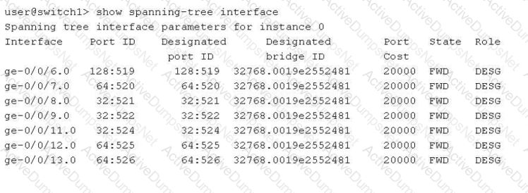
Referring to the exhibit, which two statements are correct? (Choose two.)
Options:
The switch1 device is using VSTP.
The switch1 device is the root bridge.
The ge-0/0/8, ge-0/0/9, and ge-0/0/11 interfaces are using the default interface priority.
The bridge priority for switch1 is 32k.
Answer:
B, DExplanation:
In the provided exhibit, the output of the command show spanning-tree interface for switch1 reveals critical details about the Spanning Tree Protocol (STP) operational state.
The first correct statement is thatthe switch1 device is the root bridge(Option B). This is determined by comparing the "Port ID" column with the "Designated port ID" column, as well as checking the "Designated bridge ID". In the exhibit, for every interface listed (from ge-0/0/6.0 to ge-0/0/13.0), the Port ID and the Designated port ID are identical. Furthermore, every port is in the "FWD" (Forwarding) state with the "DESG" (Designated) role. In a Spanning Tree topology, the root bridge is the only device where all active participating interfaces serve as designated ports, as it has no need for a "Root" port role (which points toward a root bridge).
The second correct statement is thatthe bridge priority for switch1 is 32k(Option D). Looking at the "Designated bridge ID" column, we see the value 32768.0019e2552481. In Junos and general networking standards, the Bridge ID is composed of a bridge priority and the device's MAC address. The default priority for most Spanning Tree variants (STP, RSTP, MSTP) is 32,768, which is commonly referred to in shorthand as "32k".
Regarding the incorrect options:
Option A:There is no evidence of VSTP (VLAN Spanning Tree Protocol); the output shows "instance 0," which is typical for IEEE standard RSTP or STP.
Option C:The Port IDs for ge-0/0/8, ge-0/0/9, and ge-0/0/11 all start with "32" (e.g., 32:521), whereas the default port priority is typically 128 (as seen in ge-0/0/6.0 with 128:519). This indicates that the interface priorities for these specific ports have been manually tuned to a non-default value.
Which statement about RSVP-signaled LSPs is correct?
Options:
CSPF is not required for LSPs using admin-groups.
CSPF is used to calculate the path for a traffic-engineered LSP.
The paths used by LSPs are always calculated using the SRGB.
The paths used by LSPs are always calculated using the TED.
Answer:
BExplanation:
In a Juniper Networks environment,Resource Reservation Protocol (RSVP)is a signaling protocol used to establish Label-Switched Paths (LSPs). While RSVP handles the actual signaling (requesting labels and reserving bandwidth along a path), it does not inherently know which path to take. This is whereConstrained Shortest Path First (CSPF)comes into play.
CSPFis an advanced version of the Dijkstra algorithm used specifically for traffic engineering. Unlike the standard SPF used by IGPs, which only considers the shortest metric, CSPF takes into account multiple constraints such as available bandwidth, link coloring (administrative groups), and explicit hop requirements. According to Juniper technical documentation, when an LSP is configured, the Ingress router uses CSPF to calculate a loop-free path that satisfies all these constraints before RSVP begins signaling. This is why statementBis the correct description of the operational flow.
StatementDis a common distractor. While CSPF uses theTraffic Engineering Database (TED)to perform its calculations, the path is not "calculated by the TED" itself; the TED is merely the repository of link-state information (provided by OSPF or IS-IS extensions). StatementCrefers to Segment Routing Global Block (SRGB), which is relevant to Segment Routing (SR-TE), not standard RSVP-signaled LSPs. Finally, statementAis incorrect because admin-groups (link coloring) are actually one of the primary constraints thatrequireCSPF to determine a valid path.
You are evaluating BGP between two Juniper routers and the BGP session is stuck in the Idle state. What would cause this behavior?
Options:
The BGP hold time is too short.
The BGP group type is set to internal instead of external.
The local AS number is missing.
The peer IP address is incorrect.
Answer:
DExplanation:
In the BGP Finite State Machine (FSM), theIdlestate is the first stage of any BGP connection. When a BGP session is "stuck" in Idle, it typically indicates that the router is unable to even begin the process of establishing a TCP connection with its neighbor. According to Juniper Networks documentation, before BGP can transition to theConnectorActivestates, it must have a valid route to the neighbor's IP address in the routing table and be able to initiate a three-way TCP handshake on port 179.
If thepeer IP address is incorrect(Option D), the router may not have a route to that destination, or it may be attempting to connect to a non-existent or unreachable host. In many Junos configurations, if the underlying IGP (OSPF/IS-IS) or static routing cannot provide reachability to the neighbor address defined in the BGP configuration, the BGP process will remain in the Idle state and periodically retry the connection.
Regarding the other options:
The local AS number is missing (Option C):In Junos, you cannot commit a BGP configuration if the local autonomous system is not defined at either the [edit routing-options] level or within the BGP group itself. The commit check would fail before the session could even attempt to start.
The BGP group type (Option B):Having a mismatch in group type (internal vs. external) usually results in the session reaching theOpenSentorOpenConfirmstate before failing due to an "unacceptable AS" error in the OPEN message.
BGP hold time (Option A):Issues with hold timers or keepalives generally cause a session that is already in theEstablishedstate to drop; they do not prevent the session from leaving the Idle state.
Unlock JN0-364 Features
- JN0-364 All Real Exam Questions
- JN0-364 Exam easy to use and print PDF format
- Download Free JN0-364 Demo (Try before Buy)
- Free Frequent Updates
- 100% Passing Guarantee by Activedumpsnet
Questions & Answers PDF Demo
- JN0-364 All Real Exam Questions
- JN0-364 Exam easy to use and print PDF format
- Download Free JN0-364 Demo (Try before Buy)
- Free Frequent Updates
- 100% Passing Guarantee by Activedumpsnet