- Home
- EMC
- Storage Administrator
- D-PST-MN-A-24
- D-PST-MN-A-24 - Dell PowerStore Maintenance Achievement
EMC D-PST-MN-A-24 Dell PowerStore Maintenance Achievement Exam Practice Test
Dell PowerStore Maintenance Achievement Questions and Answers
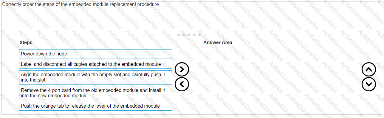
Correctly order the steps of the embedded module replacement procedure.
Options:
Answer:
Explanation:
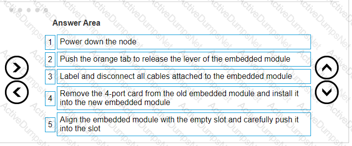
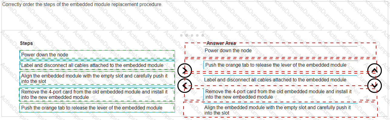
The correct order of steps for the embedded module replacement procedure is:
Power down the node
Push the orange tab to release the lever of the embedded module
Label and disconnect all cables attached to the embedded module
Remove the 4-port card from the old embedded module and install it into the new embedded module
Align the embedded module with the empty slot and carefully push it into the slot
The procedure for replacing an embedded module in a Dell PowerStore system is a critical task that should be performed with care. Here is a detailed explanation of each step:
Power down the node: Ensure that the node is properly powered down to avoid any electrical hazards or data corruption.This step is crucial for the safety of both the technician and the system1.
Push the orange tab to release the lever of the embedded module: Locate the orange tab on the embedded module and push it to release the lever.This action will unlock the module from its slot1.
Label and disconnect all cables attached to the embedded module: Before removing the embedded module, label all cables for easy reconnection later.Then, carefully disconnect each cable to free the module1.
Remove the 4-port card from the old embedded module and install it into the new embedded module: Transfer the 4-port card from the old module to the new one.Handle the card with care to avoid damage to the electronic components1.
Align the embedded module with the empty slot and carefully push it into the slot: Carefully align the new embedded module with the guides in the empty slot and gently push it into place until it is securely seated1.
After completing these steps, reconnect the cables as per the labels, and power up the node to verify the operation of the new embedded module.For detailed instructions and safety information, refer to the Dell PowerStore Installation and Service Guide2. It is important to follow these guidelines closely to ensure the replacement is performed correctly and the system operates smoothly after the procedure.
What is an alternative way to collect logs instead of using the Dell EMC PowerStore manager GUI?
Options:
Data Collect using Service Container
USB stick inserted into the system
Data Collect using vCenter
Discovery Utility
Answer:
AExplanation:
An alternative way to collect logs instead of using the Dell EMC PowerStore manager GUI isData Collect using Service Container.
The Dell EMC PowerStore provides multiple methods for collecting logs for troubleshooting and analysis.
While the PowerStore Manager GUI is a common method, using the Service Container via SSH/CLI is an alternative way to gather logs1.
This method involves connecting to the PowerStore system’s Service Container through SSH and running specific service commands to collect the required logs.
The commandssvc_dc download -horsvc_dc upload -hcan be used to download or upload logs directly from and to the system1.
This process is particularly useful when the GUI is not accessible or when directed by Dell Support to collect more detailed logs for complex issues.
For detailed instructions on log collection using the Service Container, refer to the Dell PowerStore Service Scripts Guide or contact Dell Support for assistance.
While on-site troubleshooting a Dell EMC PowerStore system, the node B embedded module fault LED is blinking blue and amber alternating at one second intervals. What doesthis indicate?
Options:
Node is in service mode
System is not initialized
Node is booting
Node is in degraded mode
Answer:
AExplanation:
When the node B embedded module fault LED on a Dell EMC PowerStore system is blinking blue and amber alternating at one-second intervals, it indicates that the node is in service mode1. Service mode is a state where the node is not in normal operation and may be undergoing maintenance or diagnostics.
In service mode, the node is typically isolated from normal storage operations to allow for troubleshooting, hardware replacement, or software updates without affecting the rest of the system. The alternating blue and amber LED is a visual indicator used by technicians to identify the current state of the node.
To return the node to normal operation, the service task must be completed, and the node must be taken out of service mode using the appropriate commands through the system’s management interface.For detailed procedures on managing nodes in service mode, refer to the Dell EMC PowerStore Service Manual or contact Dell EMC Support for guidance2.
What describes Dell EMC PowerStore X front-end cabling?
Options:
Uses internal VMware virtual switching and does not require a management network
Management and discovery use the same cables and connections as storage
Storage and management use the same LACP bonded cable connection
Uses VLTi data switch interconnectivity to support vMotion networks
Answer:
BExplanation:
The Dell EMC PowerStore X series supports Ethernet connectivity through ports on the embedded module, and on optional I/O modules1. This design allows for management and discovery to use the same cables and connections as storage.The PowerStore X models support front-end NVMe connectivity with NVMe over Fibre Channel and NVMe over TCP, providing a complete end-to-end NVMe solution2.
For the PowerStore X, the management network is integrated with the storage network, which simplifies the cabling requirements and reduces the number of separate networks that need to be maintained.This integration is particularly beneficial in VMware environments where the PowerStore X can leverage internal VMware virtual switching, which further streamlines the network infrastructure1.
In summary, the front-end cabling of the Dell EMC PowerStore X is designed to consolidate management and storage networking, which simplifies the overall network design and reduces the complexity of cable management.This approach is aligned with best practices for storage connectivity and ensures efficient use of network resources3.
A Storage Administrator needs to connect through SSH to run svc commands. How is the SSH session configured?
Options:
NAS server IP address using port 22
Appliance IP address using port 26
NAS server IP address using port 26
Appliance IP address using port 22
Answer:
DExplanation:
The SSH session for a Storage Administrator to run svc commands on a Dell EMC PowerStore system is configured using theAppliance IP address using port 22.
To connect to the service console over SSH, the Storage Administrator should use the appliance IP address.
The default SSH port for accessing the service console isport 221.
SSH access to the nodes may be required for troubleshooting and is not enabled by default. To enable SSH access:
Navigate toSettings.
SelectSSH Managementfrom the Security section.
Choose the appliance or appliances on which to enable SSH.
ClickENABLE SSH1.
The service user account is used for SSH login, and the password is set during the Initial Configuration Wizard (ICW) or can be reset from the PowerStore Manager user interface1.
It’s important to note that the SSH port used to log in to the service container is port 22 after the cluster creation is completed.Before the ICW is run, port 26 may be used1.
For detailed instructions on how to connect to the service console over SSH, please refer to the official Dell documentation or contact Dell Support for assistance.
Under which condition does the Dell EMC PowerStore equipment in the rack require additional stability?
Options:
Unstable humidity
When shipping the system
Low temperatures
High temperatures
Answer:
BExplanation:
The Dell EMC PowerStore equipment in the rack requires additional stabilitywhen shipping the system.
When preparing Dell EMC PowerStore equipment for shipping, it is crucial to ensure that the system is stable and secure to prevent any damage during transit.
Additional stability measures might include securing the equipment within the rack using appropriate brackets, using pallets designed for shipping heavy equipment, and ensuring that the rack is properly balanced.
The need for additional stability is not typically associated with environmental conditions such as humidity or temperature but is a standard precaution during the physical movement of the system to safeguard against vibrations, shocks, and impacts that can occur during shipping1.
For detailed procedures and best practices regarding the shipping and handling of Dell EMC PowerStore equipment, it is recommended to consult the official Dell EMC PowerStore documentation or contact Dell EMC support.
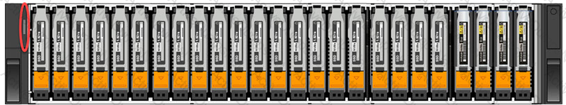
Refer to the exhibit.
What is indicated when the circled LED on the base enclosure is illuminated amber?
Options:
Cluster discovery state
Base enclosure fault
Cluster service mode
Answer:
CExplanation:
When the circled LED on the base enclosure of a Dell PowerStore system is illuminated amber, it typically indicates a fault within the base enclosure. This could be related to various issues such as power supply problems, cooling system malfunctions, or other operational faults that may affect the enclosure’s performance.
In Dell PowerStore systems, LED indicators are used to communicate the status of the system’s hardware components. An amber LED specifically suggests that there is a problem that needs to be addressed. The steps to investigate and resolve the issue usually include:
Checking the PowerStore Manager for alerts or messages that provide more details about the fault.
Inspecting the physical hardware to identify any visible signs of damage or failure.
Consulting the Dell PowerStore Hardware Guide for information on LED indicators and their meanings.
Following the recommended actions provided in the guide, which may include checking power connections, ensuring proper airflow, or other hardware checks.
If necessary, contacting Dell Support for further assistance, providing them with the details of the fault LED and any other relevant information observed.
It’s important to address any faults indicated by an amber LED promptly to maintain the integrity and reliability of the storage system. The Dell PowerStore documentation provides comprehensive information on LED indicators and troubleshooting steps to help resolve such issues effectively.
Which account credentials are needed to run diagnostic commands?
Options:
console
service
root
admin
Answer:
BExplanation:
The account credentials needed to run diagnostic commands on Dell PowerStore Maintenance are for theserviceaccount.
The service account is specifically designed for performing specialized service functions, including running diagnostic commands1.
To run service commands, you would typically:
Enable SSH in PowerStore Manager under Settings.
Use an SSH client to connect to the management IP.
Log in using the username and password for the service account2.
The service account has the necessary permissions to execute service scripts and commands that are used for diagnostics and troubleshooting3.
It is important to note that the service account password should be changed from the default during the initial configuration of the appliance for security purposes1.
For more detailed information on using the service account for diagnostics and other service tasks, refer to the Dell PowerStore Service Scripts Guide or contact Dell Support.
A Storage Administrator needs to add drives to a base enclosure of a Dell EMC PowerStore 3000X system. The system currently contains 10 750-GB NVMe SCM drives.Which
drive configuration maximizes the base enclosure capacity?
Options:
13 750-GB NVMe SCM drives in slots 10-22
11 750-GB NVMe SCM drives in slots 10-20
13 15360-GB NVMe SSD drives in slots 10-22
11 15360-GB NVMe SSD drives in slots 10-20
Answer:
CExplanation:
To maximize the base enclosure capacity of a Dell EMC PowerStore 3000X system, the best configuration would be to add the largest available NVMe SSD drives.According to the Dell PowerStore Technical Primer, before attaching an NVMe expansion enclosure, all drive slots 0 to 21 in the base enclosure must be populated1. Therefore, adding 13 15360-GB NVMe SSD drives in slots 10-22 would maximize the base enclosure capacity.
Here are the steps for this configuration:
Verify that the PowerStore 3000X system supports 15360-GB NVMe SSD drives.
Ensure that there are no existing drive compatibility issues with mixing different types and sizes of drives.
Populate slots 10 through 22 with 15360-GB NVMe SSD drives.
Follow the Dell PowerStore documentation for proper drive installation procedures to ensure system compatibility and performance1.
This configuration leverages the maximum capacity drives available for the remaining slots in the base enclosure, thus providing the greatest amount of storage space within the existing hardware constraints. It is important to consult the latest Dell PowerStore documentation to confirm compatibility and any potential firmware or software requirements for this configuration.
While on-site installing a Dell EMC PowerStore system, the node A and B embedded module fault LEDs are alternating blue and amber (blue for 3 seconds). What does this
indicate?
Options:
Nodes are in service mode
Nodes are in degraded mode
The system is not initialized
The system is booting
Answer:
CExplanation:
When the node A and B embedded module fault LEDs on a Dell EMC PowerStore system are alternating between blue and amber, with the blue LED illuminated for 3 seconds, it indicates that the system is not initialized1. This LED behavior is part of the system’s design to communicate its current state to the user or technician on-site.
The initialization process is a critical step during the installation of a PowerStore system. It involves setting up the system’s configuration, including network settings, storage pools, and other essential parameters. Until this process is completed, the system cannot perform storage operations or host any virtual machines.
To resolve this and initialize the system, the following steps should be taken:
Connect to the system through the PowerStore Manager using a supported web browser.
Complete the Initial Configuration Wizard (ICW), which guides you through the necessary steps to initialize the system.
Once the ICW is completed, the system will finalize its configuration and the LEDs should reflect a normal operational state.
For more detailed guidance on the initialization process and understanding the LED indicators, refer to the Dell PowerStore Installation and Service Guide2. This document provides comprehensive instructions on installing and configuring the PowerStore system, ensuring it is ready for use.
Which component is only replaceable by qualified personnel?
Options:
Base enclosure
Memory module
Embedded I/O module
Power supply
Answer:
AExplanation:
The base enclosure is a component that is typically only replaceable by qualified personnel. This is because the base enclosure of a Dell PowerStore system contains critical components and connections that require specialized knowledge and tools to handle properly. Replacing a base enclosure involves understanding the system’s architecture, safely disconnecting and reconnecting various components, and ensuring that the system is not compromised during the process.
The memory module, embedded I/O module, and power supply are designed to be more accessible for replacement and may fall under the category of customer-replaceable units (CRUs) or field-replaceable units (FRUs), depending on the specific model and configuration of the PowerStore system1.
For detailed procedures on replacing the base enclosure or any other components, it is recommended to refer to the official Dell PowerStore Installation and Service Guide.This guide provides step-by-step instructions and safety precautions for qualified personnel to follow when performing hardware replacements1. It is crucial to adhere to these guidelines to maintain system integrity and ensure that the storage system continues to operate effectively after the replacement.
A Storage Administrator notices two fans in a Dell EMC PowerStore are faulted. What describes the system behavior in this circumstance?
Options:
An increased fan speed signal is sent to the surviving fans and the system continues normal operations
Upon the second fan fault, all host I/O is terminated immediately and the PowerStore goes through the halt and vault process and shuts down
A five-minute timer starts upon the second fan fault and the system shuts down automatically after the timer expires
CPU clock speed is reduced by 50% to lower internal temperatures and the system continues normal operations
Answer:
AExplanation:
When two fans in a Dell EMC PowerStore system are faulted, the system’s behavior is to send an increased fan speed signal to the surviving fans to compensate for the loss and continue normal operations.This is a part of the system’s design to ensure redundancy and maintain cooling within operational parameters even when one or more fans are not functioning1.
The system monitors the health of all fans continuously. If a fan fault is detected, the system will:
Generate an alert to notify the administrator of the fault.
Increase the speed of the remaining fans to prevent overheating.
Continue to operate normally unless the temperature exceeds safe operating limits.
The administrator should then take the following steps:
Acknowledge the alert in the PowerStore Manager.
Plan for the replacement of the faulted fans as soon as possible to restore full redundancy.
Follow the replacement procedures as outlined in the Dell PowerStore Installation and Service Guide2.
It is important to address fan faults promptly to ensure the long-term health and performance of the PowerStore system. The increased fan speed is a temporary measure to maintain operations until the faulted fans can be replaced.
What is the protocol used for the storage network?
Options:
NFS
FC
iSCSI
SMB
Answer:
BExplanation:
The protocol used for the storage network in Dell PowerStore systems is Fibre Channel (FC). FC is a high-speed network technology primarily used for storage networking.Dell PowerStore utilizes FC as part of its all-NVMe design, which also includes NVMe-over-fabric networking to deliver low latency performance for storage workloads1.
Fibre Channel provides several benefits for storage networks, including:
High throughput and low latency for storage operations.
Support for long-distance networking, which is beneficial for disaster recovery and remote backups.
A mature and widely supported ecosystem with a variety of hardware and software options.
For detailed information on configuring and using FC with Dell PowerStore, administrators should refer to the Dell PowerStore Networking Guide for Storage Services and the Dell PowerStore Best Practices Guide.These documents provide comprehensive instructions on network configurations, including best practices for setting up and managing FC networks within Dell PowerStore environments23. Following these guidelines ensures optimal performance and reliability of the storage network.
What is a step in configuring the ToR data switches for a Dell EMC PowerStore T?
Options:
Configure a port for the discovery laptop
Create VLAN for vMotion networks
Configure ports for management on native VLAN
Create VLANs for NAS server networks
Answer:
AExplanation:
Configuring the Top of Rack (ToR) data switches for a Dell EMC PowerStore T involves several steps to ensure proper network setup and connectivity. One of the essential steps is to configure a port for the discovery laptop. This step is necessary for the initial discovery and configuration of the PowerStore appliances.
The process typically includes:
Identifying an unused port on the ToR switch that will be dedicated to the discovery laptop.
Configuring the identified port with the appropriate VLAN settings that match the network design of the PowerStore environment.
Ensuring that the port has the correct speed and duplex settings to communicate effectively with the discovery laptop.
Connecting the discovery laptop to the configured port to begin the discovery process of the PowerStore appliances.
This step is crucial as the discovery laptop is used to run the PowerStore Discovery Utility, which helps in identifying PowerStore appliances on the network and assists with the initial configuration1.For detailed instructions on configuring ToR switches and other networkingcomponents for PowerStore T, refer to the Dell PowerStore Networking Guide for PowerStore T Models2.
What describes Dell EMC PowerStore heat dissipation?
Options:
Lower model numbered systems have lower heat dissipation specifications than higher model numbered systems
X systems have higher heat dissipation specifics than T systems
Higher model numbered systems have lower heat dissipation specifications than lower model numbered systems
T systems have higher heat dissipation specifics than X systems
Answer:
AExplanation:
Heat dissipation in Dell EMC PowerStore systems is typically related to the power and cooling requirements of the system, which are influenced by the system’s configuration and components.Generally, lower model numbered systems, which have less processing power and storage capacity, will have lower heat dissipation specifications compared to higher model numbered systems that are more powerful and have greater storage capacity1.
The heat dissipation specification is an important factor in data center planning as it affects the environmental control requirements such as cooling and airflow. When planning for the installation of PowerStore systems, it is crucial to consider the heat output of the systems to ensure that the data center environment can maintain the optimal temperature for reliable operation.
For detailed specifications on heat dissipation for specific PowerStore models, one should refer to the official Dell EMC PowerStore Spec Sheets, which provide comprehensive information on the electrical and thermal characteristics of each model1. These documents are essential for understanding the power consumption and cooling requirements of PowerStore systems. Following the guidelines provided in these documents helps ensure that the systems are deployed in an environment that can support their thermal management needs.
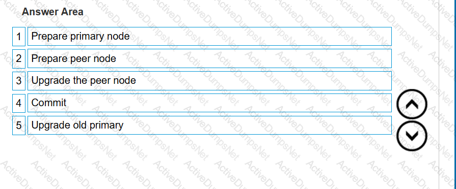
Order the NDU operational steps.
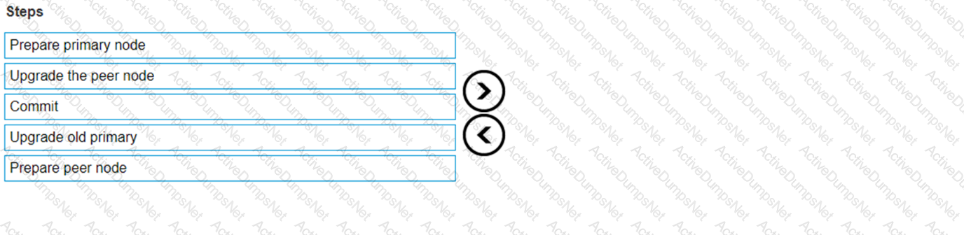
Options:
Answer:
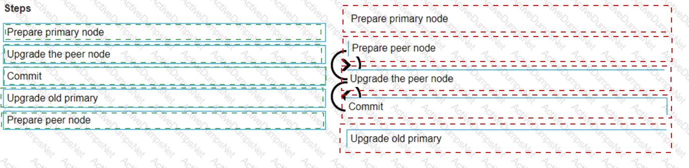
Explanation:
 A screenshot of a computer
Description automatically generated
A screenshot of a computer
Description automatically generated
What is the reason for the best practice of leaving 2 Us of space at the bottom of the rack when racking Dell EMC PowerStore systems?
Options:
Provide cooling air intake
Leave room for serviceability
Leave clearance for wheel roll
Provide better rack stability
Answer:
BExplanation:
The reason for the best practice of leaving 2 Us of space at the bottom of the rack when racking Dell EMC PowerStore systems is toleave room for serviceability.
When installing a Dell EMC PowerStore system, it is recommended to leave 2 Us of space at the bottom of the rack.
This space is not for cooling, wheel clearance, or stability, but rather to ensure that there is enough room for service activities1.
Serviceability involves the ability to access and maintain hardware components easily. The additional space allows for better maneuverability and access to the system for maintenance and repairs.
Following this best practice helps in preventing potential issues that might arise from cramped spaces, which can make it difficult to perform necessary service tasks1.
For more detailed information on installation best practices, refer to the Dell EMC PowerStore Quick Start Guide or the Best Practices Guide21.
Which number in the code-naming schema represents a beta distribution?
Options:
4
6
8
Answer:
BExplanation:
In the Dell PowerStore code-naming schema, the number that represents a beta distribution is4. This is based on the PowerStoreOS release matrix, where the versioning and distribution types are indicated by specific digits in the version number.The third digit in the version number typically represents the target code, which is a highly trusted and recommended release1.
For beta distributions, which are pre-release versions provided for testing purposes, Dell uses specific numbering conventions to distinguish them from general availability releases. These beta versions are important for testing new features and fixes in a controlled environment before they are released to all customers.
For detailed information on the code-naming schema and understanding the different types of software distributions for Dell PowerStore, including beta distributions, administrators should refer to the official Dell PowerStoreOS Matrix documentation.This document provides a comprehensive overview of the versioning system and the criteria used to determine the target code and other distribution types1.
Unlock D-PST-MN-A-24 Features
- D-PST-MN-A-24 All Real Exam Questions
- D-PST-MN-A-24 Exam easy to use and print PDF format
- Download Free D-PST-MN-A-24 Demo (Try before Buy)
- Free Frequent Updates
- 100% Passing Guarantee by Activedumpsnet
Questions & Answers PDF Demo
- D-PST-MN-A-24 All Real Exam Questions
- D-PST-MN-A-24 Exam easy to use and print PDF format
- Download Free D-PST-MN-A-24 Demo (Try before Buy)
- Free Frequent Updates
- 100% Passing Guarantee by Activedumpsnet