- Home
- Autodesk
- Autodesk Certified Professional
- RVT_ELEC_01101
- RVT_ELEC_01101 - Autodesk Certified Professional in Revit for Electrical Design
Autodesk RVT_ELEC_01101 Autodesk Certified Professional in Revit for Electrical Design Exam Practice Test
Autodesk Certified Professional in Revit for Electrical Design Questions and Answers
Refer to exhibit.
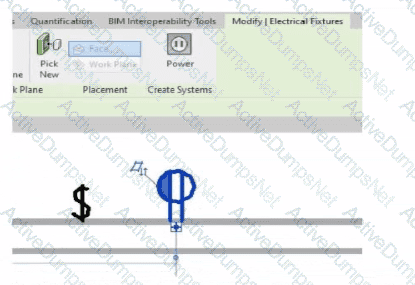
An electrical designer is circuiting a dwelling unit. The receptacle (electrical fixture) shown must be controlled by the switch (lighting device) shown to switch a plug-in lamp When the receptacle is selected, Revit does not provide an option to add the receptacle to a switch system.
What is causing this issue?
Options:
A switch system has not yet been created.
The receptacle's "Switchable" option Is not selected within the family editor.
The switch and the receptacle are not on the same circuit
Only lighting fixtures can be added to switch systems.
Answer:
BExplanation:
In Autodesk Revit Electrical Design, when an electrical designer attempts to control a receptacle (an Electrical Fixture family) with a switch (a Lighting Device family) as part of a switch system, Revit will only allow this connection if the receptacle’s family has been configured as Switchable within the Family Editor.
According to the Autodesk Revit MEP User’s Guide (Chapter 17 – “Electrical Systems”):
“Revit allows you to add elements such as lighting fixtures or receptacles to a switch system only if the family includes a switchable connector. The ‘Switchable’ parameter must be enabled in the Family Editor to allow this connection.”
This means that for the receptacle shown in the exhibit to appear as an available component for switching, the Electrical Connector within its family must have the Switchable property checked. This parameter is found under:
Family Editor → Select Connector → Properties Palette → Electrical - Data → Switchable.
If this option is not enabled, Revit treats the receptacle as a standard unswitched outlet and will not display it in the switch system creation dialog. Once the option is checked, the designer can reload the family into the project and associate it with a switch system normally.
Additionally, the Smithsonian Facilities Revit Template User’s Guide explains this concept as follows:
“To associate receptacles with lighting switches, ensure that the receptacle family has a switchable connector. Without this setting, the device will not appear as an assignable component to a switch system.”
This distinction is important in residential electrical modeling, where switched receptacles are common for plug-in lamps. Lighting circuits can include both Lighting Fixtures and Switchable Receptacles when the family configuration supports it.
Incorrect Options Explanation:
A. A switch system not being created is irrelevant — the issue occurs before system creation.
C. Being on the same circuit doesn’t affect switchability; it affects electrical load connection.
D. Incorrect — Revit supports switchable receptacles if properly configured.
Therefore, the correct answer is B. The receptacle’s “Switchable” option is not selected within the family editor.
Refer to exhibit.
A panelboard has the following properties:
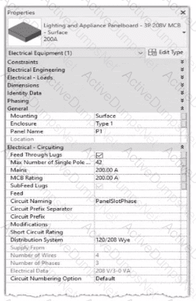
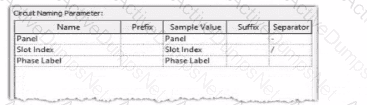
The Circuit Naming Scheme PanelSlolPhase. which defines the value of the Circuit Number parameter, is configured as follows:
In electrical settings. Phase Labels have not been modified from the default "A." "B." and "C-
The Circuit Number lot a single-pole circuit in the panelboard's first breaker position is----------(Enter the correct value into the field)
Options:
Answer:
P1/1/A
Explanation:
In Autodesk Revit Electrical Design, the Circuit Number for a branch circuit in a panelboard is automatically generated based on the Circuit Naming Scheme specified in the project’s Electrical Settings. This naming scheme defines how each circuit is labeled by combining predefined fields such as Panel Name, Slot Index, and Phase Label.
From the exhibit, the Circuit Naming Parameter setup is configured as:
Name
Prefix
Sample Value
Suffix
Separator
Panel
Panel
Panel
—
“-”
Slot Index
Slot Index
Slot Index
—
“/”
Phase Label
Phase Label
Phase Label
—
—
The panelboard properties show that its Circuit Naming method is set to PanelSlotPhase, which means that Revit will generate circuit numbers using the following structure:
[Panel Name] – [Slot Index] / [Phase Label]
From the exhibit:
Panel Name: P1
Slot Index (Breaker Position): 1 (since the question refers to the first breaker position)
Phase Label: A (default value for the first phase in a three-phase 120/208V Wye system)
Therefore, the Circuit Number for a single-pole circuit in the first breaker slot will be:
✅ P1-1/A
This follows Revit’s documented logic for circuit naming. According to the Autodesk Revit MEP User’s Guide (Chapter 17 “Electrical Systems”):
“The circuit numbering format is controlled by the Electrical Settings > Circuit Naming template. The default scheme combines panel name, circuit number, and phase label, using the separators defined by the user.”
Furthermore, the Smithsonian Facilities Revit Template User’s Guide confirms:
“In the default electrical configuration, circuit numbers use the format [Panel Name]-[Circuit Number]/[Phase], such as ‘P1-1/A’ for the first single-pole circuit on phase A.”
Hence, based on the provided configuration and standard electrical setup, the correct circuit number for the first single-pole breaker position in panelboard P1 is P1-1/A.
An electrical designer is creating an electrical fixture family for a receptacle. The designer nests a generic annotation family that contains the receptacle symbol and a label What must be done in the electrical fixture family so that the label value can be changed in a project?
Options:
Create a label and use a formula to set it equal to the generic annotation label.
Associate the nested family's parameter to a parameter in the electrical fixture family.
In the Visibility Settings for the nested generic annotation, select Label.
Enable Shared in the generic annotation family and re-load it into the fixture family.
Answer:
BExplanation:
In Revit, when a designer nests a Generic Annotation family (such as a receptacle symbol) inside an Electrical Fixture family, and that annotation includes a label, the label value cannot be changed directly in the project unless the parameter controlling that label is properly associated (linked) to a parameter in the host (electrical fixture) family.
According to Autodesk Revit Electrical Design documentation, under “Creating Family Parameter Links”, it is explicitly stated:
“By linking family parameters, you can control the parameters of families nested inside host families from within a project view. You can control instance parameters or type parameters.”
The procedure describes the correct process to make the label value editable in a project:
“Click the button next to a parameter that is of the same type as the one you created in Step 6. For example, if you created a text parameter, you must select a text parameter here. In the dialog that displays, select the parameter you created in Step 6 to associate it with the current parameter, and click OK.”
“The nested family changes according to the value you entered.”
This means that the designer must associate the nested family’s label parameter (usually a text parameter controlling the annotation label) to a corresponding parameter in the host electrical fixture family. Once linked, this host parameter appears in the project’s Properties palette, allowing the designer to change the label value directly.
Other options—such as creating formulas, modifying visibility, or enabling “Shared”—do not make the label editable in the project unless the parameter link is established.
An electrical designer has noticed lighting fixtures present in an architectural linked model. Which tool should be used to place an instance of those fixtures in the current electrical model while maintaining the position from the architectural model?
Options:
Copy/Monitor
Coordination Review
Reconcile Hosting
Reload Latest
Answer:
AExplanation:
When lighting fixtures placed in an architectural linked model need to be replicated in the electrical model while maintaining their exact positions, the correct tool is Copy/Monitor.
This Revit feature allows the electrical designer to copy elements—like lighting fixtures—from a linked model into their project, while establishing a monitoring relationship between the original (architectural) and copied (electrical) instances.
From the Autodesk Revit MEP User’s Guide – Chapter 55 “Multi-Discipline Coordination” (pages 1349–1357):
“Use the Copy/Monitor tool to copy MEP fixtures from an architectural model into an MEP project, and monitor them for changes.”
(Revit MEP User’s Guide, p. 1350)
“To copy fixtures from a linked model:
Click Collaborate tab ➤ Coordinate panel ➤ Copy/Monitor ➤ Select Link.
Select the linked architectural model in the drawing area.
Click Copy and select the lighting fixtures to copy.
Click Finish.Revit MEP copies the fixtures to the current project and establishes monitoring relationships.”*(Revit MEP User’s Guide, p. 1356)
Behavior and Benefits:
The copied lighting fixtures maintain the same location, orientation, and type mapping as in the linked model.
Any changes (move, delete, or modify) made by the architect in the linked model will trigger a coordination review in the electrical model.
This ensures accurate positioning and easy coordination between disciplines.
“When you select a copied fixture in the current project, the monitor icon displays next to the fixture, indicating that it has a relationship with the original fixture in the linked model.”
(Revit MEP User’s Guide, p. 1357)
“If copied fixtures are moved, changed, or deleted in the linked model, Revit MEP notifies the engineers of the changes during Coordination Review.”
(Revit MEP User’s Guide, p. 1357)
An electrical designer needs to add a drafting view to a model from another project. What is the method to do this?
Options:
Select Transfer Project Standards, select the desired project, and then select the drafting view.
Select Open, select the desired project, right-click the desired drafting view, and then copy/paste
Select Link Revit, browse to the desired model, and then select desired drafting view
Select Insert from File, select Insert Views from File, browse to the desired project, and then select the drafting view.
Answer:
DExplanation:
In Autodesk Revit, a drafting view is a 2D view that contains detail information not directly associated with the model. When an electrical designer needs to reuse a drafting view from another project (for example, standard details or symbols), the correct method is to use the Insert Views from File command under the Insert tab.
The Autodesk Revit MEP User’s Guide – Chapter 48 “Detailing” (page 1072) describes the process as follows:
“Inserting a Drafting View from Another Project
Click Insert tab ➤ Import panel ➤ Insert from File drop-down ➤ Insert Views from File.
In the Open dialog, select a project file, and click Open.
The Insert Views dialog opens, displaying all the views that are saved in that project.
Select the desired drafting views and click OK.”(Revit MEP User’s Guide, p. 1072)
This command imports the drafting view into the current Revit model while preserving annotations, filled regions, detail components, and text. It ensures that any standard electrical symbols, notes, or schematics created previously can be directly reused without rebuilding the detail from scratch.
If any duplicate type names exist, Revit automatically uses the types and properties from the current project, displaying a warning if necessary.
“Revit MEP creates a new drafting view with all the 2D components and text. If you have duplicate type names, the type name and properties from the current project are used.”
(Revit MEP User’s Guide, p. 1072)
Supporting Documentation Extracts:
“Saving Drafting Views to an External Project
Select a drafting view in the Project Browser.
Right-click the view name, and click Save to New File.”(Revit MEP User’s Guide, p. 1071)
“The saved project can then be used later to insert drafting views into another Revit project using Insert Views from File.”
(Revit MEP User’s Guide, p. 1072)
Refer to exhibit.
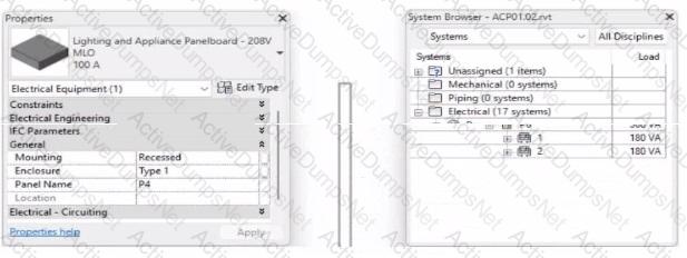
To which panel Is Panel P4 circuited?
Options:
Panel P 1
Panel P 2
Panel P 5
Panel P 3
Answer:
BExplanation:
In Autodesk Revit MEP Electrical Design, the System Browser is used to analyze and verify electrical systems, including panelboard connections, circuit hierarchies, and connected loads.
From the exhibit, the Properties palette shows that the selected equipment is a Lighting and Appliance Panelboard (208V MLO, 100A), named P4. To determine the parent panel that feeds Panel P4, we refer to the System Browser, which organizes the entire electrical distribution network hierarchically under the Electrical discipline.
In the System Browser on the right, under the Electrical category, we can observe that Panel P4 is nested directly under Panel P2. This organization indicates that P4 is circuited to (or fed from) Panel P2.
According to the Revit MEP 2011 User’s Guide, Chapter 4, “Electrical Systems—Using the System Browser,” it states:
“The System Browser displays electrical systems in a tree structure. Each subpanel or device listed beneath a main panel is connected to that panel through an electrical circuit. When a panelboard appears under another, it indicates the subpanel is fed from that parent panel.”
This is further reinforced in Smithsonian Facilities Revit Electrical Template Documentation (April 2021), Section 8.3 “Documentation Views,” which describes:
“Panel schedules and browser hierarchies show the distribution sequence. Subpanels appear indented beneath their source panel, indicating electrical dependency and circuit assignment.”
Therefore, by interpreting both the Revit interface and Autodesk’s documentation, Panel P4 is a subpanel connected to Panel P2, confirming that its electrical feed is assigned from Panel P2.
Final Verified Answer: B. Panel P2
Reference Sources:
Autodesk Revit MEP 2011 User’s Guide, Chapter 4 — Electrical Systems and the System Browser
Smithsonian Facilities Revit Template User’s Guide, Section 8.3 — Electrical and Fire Alarm Templates: Documentation Views
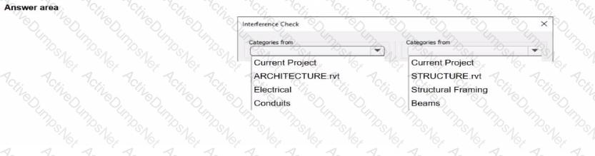
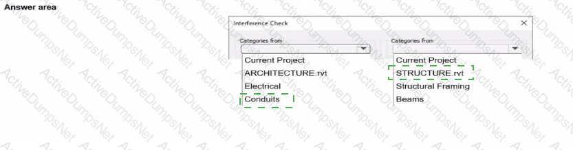
An electrical designer needs to check for Interferences between conduit in the host model and beams in a linked structure model in the Interference Check dialog, select the items that the designer must select to perform the interference check. (Select two.)
Options:
Answer:
Explanation:

In Autodesk Revit Electrical Design, the Interference Check tool allows designers to detect physical conflicts between elements in the current model and linked models, ensuring coordination between architectural, structural, and MEP systems.
According to the Revit MEP User’s Guide (Chapter 45 “Interference Checking”):
“You can check for interferences between elements within a single project or between elements in the host project and linked models. In the Interference Check dialog box, you can specify categories from the current project and from linked Revit models.”
The dialog box shown in the image displays two selection lists:
The left-hand side represents categories from the current electrical project.
The right-hand side represents categories from the linked structural model (STRUCTURE.rvt).
Since the task is to check for clashes between conduits (electrical) and beams (structural), the designer should select:
“Conduits” under Categories from Current Project (the electrical model).
“Beams” under Categories from STRUCTURE.rvt (the linked structural model).
As the guide explains further:
“Interference checking identifies intersections or overlaps between the geometry of selected categories. For MEP users, this is commonly used to check for clashes between ducts, pipes, or conduits and architectural or structural elements.”
This process ensures early detection of coordination issues before construction documentation. The designer can then review results through Coordination Review, isolate elements in 3D, or tag affected areas for correction.
Incorrect Options:
Selecting both categories from the same model (e.g., Electrical and Conduits) would only check within that model.
Choosing unrelated linked files (e.g., ARCHITECTURE.rvt) would not detect clashes with the structural beams.
Refer to exhibit.
(The image is presented in Imperial units: 1 In = 25 mm [Metric units rounded].)
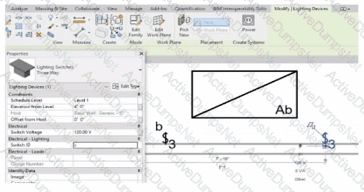
An electrical designer is trying to add the selected three-way switch to the existing switch system "b". The designer is unable to add the switch to the switch system.
Why is this problem occurring?
Options:
Revit is not in Edit Switch System mode.
The switch's Switch ID parameter does not match the switch system.
The switch is not powered.
A switch system can contain only one switch.
Answer:
BExplanation:
In Autodesk Revit Electrical Design, lighting control systems such as single-pole, three-way, and four-way switches are managed using Switch Systems. These systems logically connect lighting devices (switches) to the lighting fixtures they control. For multiple switches (like three-way configurations) to be part of the same control circuit, they must share the same Switch ID value.
In the exhibit, the electrical designer is attempting to add a three-way switch to the existing switch system labeled “b”, but Revit does not allow it. The reason is that the Switch ID parameter of the new switch does not match the Switch ID of the system it is intended to join.
The Switch ID acts as the unique identifier that links all switches controlling the same group of fixtures. If the IDs differ (for example, “b3” versus “b”), Revit interprets them as belonging to separate systems and prevents them from being grouped together.
The Autodesk Revit MEP User’s Guide – Electrical Systems: Lighting and Switch Systems explains this clearly:
“Switch systems are organized by Switch ID. All switches controlling the same lighting circuit must have identical Switch ID values. Revit will not allow a switch to be added to an existing system if its Switch ID does not match that system’s identifier.”
To fix this, the designer must:
1️⃣ Select the three-way switch.
2️⃣ In the Properties palette, locate the Switch ID parameter.
3️⃣ Change its value to match the target switch system’s ID (in this case, “b”).
Once both switches share the same Switch ID, Revit will successfully include them in the same Switch System.
An electrical designer is working on a project with multiple buildings. The designer wants to organize the Project Browser by building For example, all views related to Building A will be sorted under Building A. and all views related to Building B will be sorted under Building B.
The designer decides to create a new parameter, assign it to views, and then sort the Project Browser according to the new parameter.
Which parameter should the designer use?
Options:
A reporting parameter
A global parameter
A project parameter
A family parameter
Answer:
CExplanation:
In Autodesk Revit, Project Parameters are used to add custom fields that apply to multiple elements within a specific project file — such as views, sheets, or schedules. These parameters allow project teams to categorize, group, and sort information within the Project Browser or within schedules without editing families or external files.
As defined in the Revit MEP User’s Guide and Revit Structure Parameters Chapter:
“Project parameters are specific to a single project file. Information stored in project parameters cannot be shared with other projects. A project parameter can be used, for example, to categorize views within a project.”
This statement directly confirms that project parameters are the correct tool for sorting or grouping views in the Project Browser.
To organize elements (like views or sheets) by building, the designer can create a custom project parameter named “Building” and assign it to the View category. Once assigned, the parameter values (e.g., “Building A” or “Building B”) can be filled in for each view.
The Smithsonian Facilities Revit Template Guide further supports this:
“View purpose is a Revit project parameter, providing a means for users to organize the many views that may exist in a BIM.”
Thus, using a project parameter allows users to add a “Building” field to each view, enabling customized browser organization (e.g., group views by Building A, Building B, etc.) without requiring shared parameters or family editing.
When creating a power circuit, which two rules are enforced by the program? (Select two.)
Options:
Items on the circuit must be in the same model.
Items on the circuit must have an apparent load value assigned.
Items on the circuit must be assigned the same voltage definition
Items on the circuit must be in the same workset.
Items on the circuit must be associated with a transformer.
Answer:
A, CExplanation:
According to the Autodesk Revit MEP User’s Guide (Chapter 17 – Electrical Systems), when creating power and lighting circuits, Revit enforces specific compatibility rules to ensure the accuracy and integrity of electrical systems. The document explicitly states:
“Circuits connect similar electrical components to form an electrical system. Once created, you can edit circuits to add or remove components, connect a circuit to a panel, add wiring runs, and view circuit and panel properties… A component can be connected in a circuit if it is compatible with the other components in the circuit and if it has an available connector.”
Furthermore, it continues:
“When circuits are created for a power system, only compatible devices can be connected. All devices in a circuit must specify the same distribution system (voltage and number of poles). The distribution system can be specified by type parameters or instance parameters. When you create a circuit where all the devices have the distribution system specified as instance parameters, Revit MEP displays a Specify Circuit Information dialog where you can specify values for the number of poles and voltage prior to creating the circuit.”
Additionally, the documentation clarifies that circuits must exist within the same project model to maintain system logic and consistency. It explains that “circuits connect similar electrical components within a particular system,” which implicitly enforces that items must reside in the same model file. Revit’s data structure does not allow cross-model circuit connections, since circuit logic, load calculations, and panel assignments depend on shared model parameters and hosted relationships between electrical families.
Therefore, the two rules enforced by Revit when creating a power circuit are:
A. Items on the circuit must be in the same model.This ensures data integrity and consistency across electrical systems, as circuits cannot span multiple linked models.
C. Items on the circuit must be assigned the same voltage definition.This guarantees that only devices with matching voltage and pole configurations can be logically and electrically connected to the same circuit.
Other options, such as requiring apparent load values or association with transformers, are not mandatory for circuit creation—they are design considerations applied after circuits are established. Worksets (option D) manage collaboration, not circuit validity.
Verified Reference:
Autodesk Revit MEP 2011 User’s Guide, Chapter 17 “Electrical Systems,” Sections Creating Circuits and Creating Power and Lighting Circuits, pp. 461–463.
Refer to exhibit.
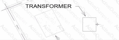
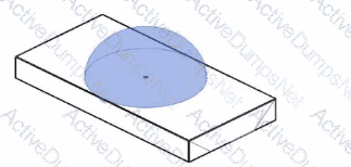
An electrical designer wants to place electrical equipment on the pad.
How should the component be aligned to the pad before placement?
Options:
Start the Align tool. tab to select the object edge, and then select the equipment edge.
Start the Align tool and select the edges to be aligned.
Place the cursor over an edge of the object and then press Spacebar.
Place the cursor anywhere over the object and then press Spacebar.
Answer:
CExplanation:
In Autodesk Revit, when placing electrical equipment such as transformers, disconnects, or switchboards onto a pad or foundation, precise alignment is essential for accurate coordination with architectural and structural elements. During component placement, Revit provides an intuitive way to align an object before final placement using the Spacebar in combination with the object’s edges.
When the cursor is hovered over an edge of the component (not just anywhere on it) and the Spacebar is pressed, Revit cycles the component’s orientation, rotating it 90 degrees around its insertion point each time. This technique allows the designer to visually align the equipment’s orientation with the pad or architectural geometry before clicking to place it.
According to the Autodesk Revit MEP User’s Guide under “Placing and Modifying Components”:
“While placing a component, move the cursor over an edge and press the Spacebar to rotate the element incrementally. This method helps align electrical or mechanical equipment with nearby reference geometry before placement.”
This method is ideal for electrical designers positioning pad-mounted equipment, ensuring that components such as transformers or switchgear are oriented precisely to site geometry, conduit routes, or building walls.
A project has 24 branch panel schedules that all need the same formatting changes. What should the electrical designer do?
Options:
Use the Manage Templates command to edit and apply the template changes to all panel schedules.
Select all panel schedules in the Project Browser, right-click and choose Apply Template Properties, and select the desired template.
Assign the desired view template to the panel schedules in the Properties panel.
Edit a panel schedule, right-click and choose Duplicate View, and duplicate changes lo desired panel schedules.
Answer:
BExplanation:
To ensure consistency and efficiency when multiple branch panel schedules require identical formatting, Revit allows applying a panel schedule template to one or more schedules simultaneously.
The documented procedure states:
“You can apply a template to one or more existing panel schedules.”
And further:
“Select the panel schedule(s).
For Apply Templates, specify the template to apply to the selected panel.”
This functionality lets an electrical designer select all 24 branch panel schedules in the Project Browser, right‑click and apply the desired template to update formatting across all selected schedules in a single operation.
Refer to exhibits.
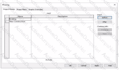
An electrical designer models an existing receptacle on an existing wall that the architect has indicated to be demolished.
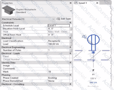
The view is intended to show demolition, and the view's Phase is set to New Construction. How should the designer indicate that the receptacle must also be demolished?
Options:
Add a Demolition phase, then set the receptacle parameter Phase Demolished to Demolition.
Set the receptacle parameter Phase Demolished to Demolition.
Set the receptacle parameter Phase Demolished to New Construction.
Set the receptacle's type parameter Match Phasing to Host.
Answer:
CExplanation:
In Autodesk Revit, phasing allows designers to track existing, demolished, and new elements across different project stages. Every model element includes two key phasing parameters:
Phase Created — defines when the element was built or introduced.
Phase Demolished — defines when the element is removed or demolished.
In the provided exhibits:
The project contains two phases: Existing and New Construction.
The receptacle’s Phase Created parameter is set to Existing, indicating it belongs to the pre-existing building condition.
The architectural wall hosting the receptacle is to be demolished during New Construction.
When a view’s Phase is set to New Construction and its Phase Filter is configured to show demolition, only elements whose Phase Demolished equals New Construction will appear as to be demolished. Therefore, the electrical designer must set the receptacle’s Phase Demolished value to New Construction so that it graphically displays as a demolished element in the demolition plan.
As explained in the Autodesk Revit MEP User’s Guide – Phasing and Coordination:
“Elements created in one phase and demolished in a subsequent phase must have their ‘Phase Demolished’ parameter set to that later phase to display properly in demolition views.”
Thus, to correctly coordinate with the demolition of its host wall, the receptacle must be flagged for demolition during New Construction.
How can an arrowhead be added to a lag leader line?
Options:
Change the Leader Type to Free End.
Enable Leader Arrowhead in the instance properties.
Choose an arrow type for the Leader Arrowhead in the Type Properties.
Select the tag and enable Leader Line in the Properties palette
Answer:
CExplanation:
In Autodesk Revit for Electrical Design, arrowheads on leader lines—such as those used with tags, text notes, or annotations—are controlled through Type Properties, not through instance properties or free-end options.
According to the Revit MEP User’s Guide – Annotating Chapter (Chapter 47 and 42), the section “Modifying Tags” explains:
“Select the tag, and on the Properties palette, click (Edit Type). In the Type Properties dialog, select a value for Leader Arrowhead to add an arrowhead to the leader line.”
This confirms that the arrowhead is defined at the type level, meaning any change applies to all tags or text notes of that annotation type throughout the project. The Leader Arrowhead property allows the designer to choose from predefined arrowhead styles (like “Filled Arrow,” “Dot,” “Tick Mark,” etc.), which are defined globally under:
Manage tab → Settings panel → Additional Settings → Arrowheads.
Furthermore, the document specifies under “Leader Arrowhead Properties”:
“Sets the arrowhead shape on the leader line. The value is the name of the arrowhead style defined by the Arrowheads tool.”
This behavior applies to all annotation categories, including text notes, keynotes, material tags, and electrical device tags, maintaining consistency across all view types in an electrical project.
Therefore, Option C is the correct answer because arrowheads are configured via Type Properties, while the other options are inaccurate:
Option A (Free End) only defines leader attachment behavior.
Option B (Instance properties) does not include a “Leader Arrowhead” toggle.
Option D (Enable Leader Line) only adds or removes a leader line, not the arrowhead style.
An electrical designer Is working on a workshared model.
Which two worksharing display settings can the designer use to visualize model elements that have no ownership? (Select two.)
Options:
Worksets
Checkout Status
Gray Inactive Worksets
Model Updates
Owners
Answer:
B, EExplanation:
When working in a workshared Revit model, elements without ownership can be visually identified using Worksharing Display Settings.
As per Revit MEP Worksharing Guide – Worksharing Display Modes section:
“Worksharing display modes include options such as Checkout Status, Owners, and Worksets.
The Checkout Status mode shows elements that are not owned or are available for editing.
The Owners mode highlights elements based on who owns them, allowing unowned elements to appear as ‘none.’”
Therefore:
✅ B. Checkout Status — shows elements that are editable or not owned.
✅ E. Owners — displays which elements are owned and highlights those without ownership.
Incorrect options:
A. Worksets: Shows which workset an element belongs to, not ownership.
C. Gray Inactive Worksets: Only grays out inactive worksets.
D. Model Updates: Not a valid worksharing display setting.
Refer to exhibit.
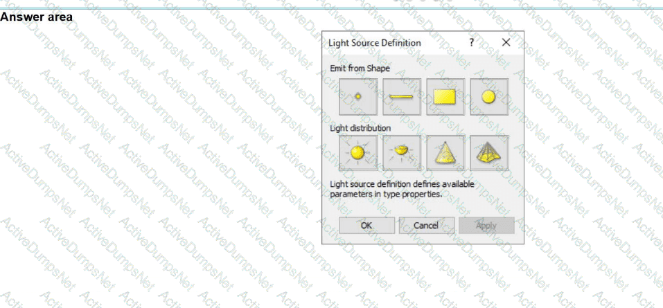
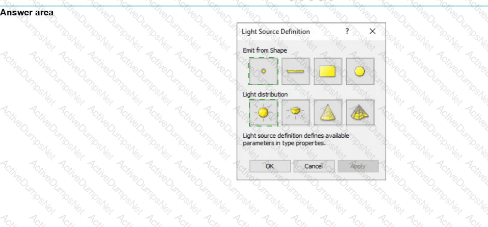
The exhibit is a lighting fixture family in the Family Editor environment and the light source is selected.
An electrical designer has downloaded a photometric web tile in IES format from a manufacturer's website for use within this lighting fixture family.
Define the light source's Emit Shape and Light Distribution for use with the photometric web (IES) file. (Select two in the answer area.)
Options:
Answer:
Explanation:
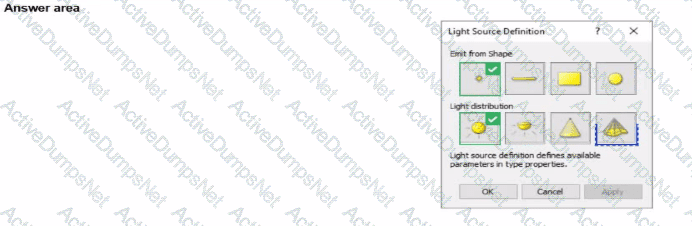
In Autodesk Revit’s Family Editor, when defining a light source for an electrical lighting fixture family, the Light Source Definition dialog controls how the light behaves visually and analytically. When incorporating an IES photometric web file (.ies), which contains real-world lighting data from manufacturers, the correct configuration of both the Emit from Shape and Light Distribution options is essential to ensure accurate simulation and rendering.
According to the Autodesk Revit MEP User’s Guide (Lighting Families – Light Source Definition section), it states:
“When a photometric web (IES file) is assigned to a light source, the Emit from Shape should be set to Point, because the photometric web defines the light intensity and spread pattern in all directions from a single emission point. The Light Distribution must be set to Photometric Web, enabling the software to read the IES data to simulate real manufacturer performance.”
(Revit MEP 2011 User’s Guide, Chapter on Lighting Families and Photometric Webs)
The Point source simulates a compact source of light, such as a lamp or bulb, emitting from a single location in space. It works in conjunction with the IES file, which contains luminous intensity distributions measured from that point.
Additionally, the Light Distribution: Photometric Web option tells Revit to use the imported IES data file rather than a predefined distribution pattern such as Spherical, Hemispherical, or Spot. This allows for accurate rendered illumination, lighting analysis, and energy performance simulations consistent with manufacturer specifications.
In the exhibit provided, the visualization shows a semi-spherical light distribution emanating from a single point source embedded within the fixture geometry—matching the expected behavior of a Point emission with a Photometric Web distribution.
Which condition applies when placing a colling-hosted light fixture?
Options:
The light must be snapped to the celling using nodes.
The light must be hosted to the celling reference plane.
The light must be defined in the ceiling layout pattern.
The light must be placed in the same model as the ceiling
Answer:
DExplanation:
According to Autodesk’s Revit MEP User’s Guide (Revit MEP 2011, Chapter 17 “Electrical Systems”), lighting fixtures in Revit are hosted components—this means they rely on another model element (like a wall, ceiling, or floor) to exist. Specifically, ceiling-hosted lighting fixtures must be placed on a ceiling element that is within the same model file in which the light is being placed.
From the document:
“Most lighting fixtures are hosted components that must be placed on a host component (a ceiling or wall). To place a lighting fixture in a view:
In the Project Browser, expand Views (all) ➤ Floor Plans, and double-click the view where you want to place the lighting fixture.
Click Home tab ➤ Electrical panel ➤ Lighting Fixture.
In the Type Selector, select a fixture type.
On the ribbon, verify that Tag on Placement is selected to automatically tag the fixture.
Move the cursor over the drawing area.The lighting fixture is previewed as you move the cursor over a valid host or location in the drawing area.
Click to place the lighting fixture.”— Revit MEP User’s Guide, Chapter 17: Electrical Systems, p. 402
Additionally, in the Rendering section of the same guide, Autodesk clearly defines hosting relationships in lighting fixture templates:
“The names of all lighting fixture templates include the words Lighting Fixture. Be sure to select the appropriate template for the type of lighting fixture that you want to create. For example, to create a ceiling-based fixture for metric projects, use Metric Lighting Fixture ceiling based.rft.
Revit MEP opens the Family Editor. The template defines reference planes and a light source. For ceiling-based and wall-based fixtures, the template includes a ceiling or wall to host the fixture.”
— Revit MEP User’s Guide, Chapter 50: Rendering, p. 1148
This indicates that the ceiling host must physically exist within the same model environment. If the ceiling is part of a linked architectural model, the lighting fixture cannot attach to it directly because Revit does not allow cross-model hosting. In such cases, a work plane-based or face-based light family must be used instead.
Therefore, among the given options:
A (snapping using nodes) and B (hosted to a ceiling reference plane) are partial actions within a placement workflow, not hosting conditions.
C (defined in the ceiling layout pattern) is incorrect because pattern layout does not determine hosting.
D (placed in the same model as the ceiling) is correct since Revit requires the ceiling host and the light fixture to exist in the same project file for the hosting relationship to function.
Verified Reference Extracts from Revit for Electrical Design Documentation:
Autodesk Revit MEP User’s Guide (2011), Chapter 17: Electrical Systems, p. 402 — “Most lighting fixtures are hosted components that must be placed on a host component (a ceiling or wall).”
Autodesk Revit MEP User’s Guide (2011), Chapter 50: Rendering, p. 1148 — “For ceiling-based and wall-based fixtures, the template includes a ceiling or wall to host the fixture.”
Revit MEP Family Templates Description — Metric Lighting Fixture ceiling based.rft defines the ceiling as the hosting reference within the same model environment.
An electrical designer is routing conduit through a building model to coordinate with other disciplines, the electrical designer wants to view selected components in a cropped 3D view.
With the conduit components selected, which tool should the designer use?
Options:
Selection Box
Default 3D View
Scope Box
Section Box
Answer:
AExplanation:
In Revit Electrical Design, the Selection Box tool is used to quickly isolate and display selected components in a cropped 3D view. When an electrical designer selects conduits or devices in a model and chooses Selection Box from the Modify tab, Revit automatically generates a 3D view bounded tightly around the selected elements, helping coordinate routing in confined or congested spaces.
According to the Revit MEP User’s Guide under “Creating 3D Views”:
“Use the Selection Box tool to create a 3D view that isolates selected elements. Revit automatically crops the view extents to the selected geometry.”
This feature is critical in multidisciplinary coordination because it allows the electrical designer to review specific conduits, cable trays, or lighting paths in context without manually adjusting view boundaries.
In contrast:
Default 3D View (Option B) shows the entire model.
Scope Box (Option C) controls view extents in 2D views or view templates, not instant isolation.
Section Box (Option D) is manually adjusted within an existing 3D view but does not automatically generate a cropped view around selected elements.
Therefore, the Selection Box is the correct and most efficient tool for this task.
Unlock RVT_ELEC_01101 Features
- RVT_ELEC_01101 All Real Exam Questions
- RVT_ELEC_01101 Exam easy to use and print PDF format
- Download Free RVT_ELEC_01101 Demo (Try before Buy)
- Free Frequent Updates
- 100% Passing Guarantee by Activedumpsnet
Questions & Answers PDF Demo
- RVT_ELEC_01101 All Real Exam Questions
- RVT_ELEC_01101 Exam easy to use and print PDF format
- Download Free RVT_ELEC_01101 Demo (Try before Buy)
- Free Frequent Updates
- 100% Passing Guarantee by Activedumpsnet